Free kVAR to kW conversion tool explained for engineers, electricians, and power systems analysts professionals.
Calculate kW from kVA quickly by applying power factor; precise, repeatable results for load balancing.
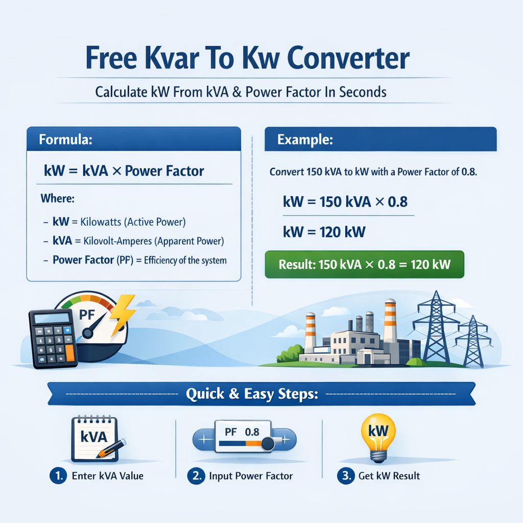
kW Calculator from kVAr, kVA and Power Factor (Instant Electrical Power Converter)
Fundamental relations between kVA, kW, and kVAR
Electric power engineering uses three interrelated quantities: active power (kW), reactive power (kVAR), and apparent power (kVA).
These are related by the power triangle and the trigonometric relationship determined by the power factor.
Core formulas
Variable definitions and typical values
- kW — kilowatts, real (active) power delivered to resistive portion of load (typical industrial motors: 0.7–0.95 PF when unloaded or lightly loaded).
- kVAR — kilovolt-ampere reactive, reactive power associated with magnetic and capacitive fields (motors, transformers, capacitors for PF correction).
- kVA — kilovolt-amperes, apparent power magnitude of the complex power vector (equipment rating often specified in kVA).
- PF — power factor, dimensionless ratio between 0 and 1. Typical values: resistive heating ~1.0, lighting old fluorescent ~0.6–0.85, induction motors 0.7–0.95.
- phi — phase angle between voltage and current; PF = cos(phi), sin(phi) and tan(phi) used to transform between kW and kVAR.
Why convert kVAR to kW (and vice versa) quickly
Designers, commissioning engineers, and operators require fast conversions for switchgear sizing, capacitor design, and energy billing analysis.
A reliable calculator reduces iteration time and avoids undersized equipment or inaccurate power factor compensation.
Application scenarios
- Specifying generator kVA rating when required kW is known and PF is expected.
- Determining required capacitive kVAR to raise PF for a given kW load.
- Estimating real power reduction when switching in/out reactive compensation.
- Verifying vendor equipment ratings and ensuring compliance with grid interconnect requirements.
Algorithm used by the free converter
The converter supports three common input combinations and returns the missing quantities:
- Input: kVA and PF → Output: kW and kVAR.
- Input: kVAR and kVA → Output: kW and PF.
- Input: kVAR and PF → Output: kW and kVA.
Step-by-step algorithm (mathematical)
- If inputs are kVA and PF:
- Compute kW = kVA × PF.
- Compute kVAR = sqrt(kVA^2 - kW^2).
- Assign sign (lagging/leading) according to load characteristic.
- If inputs are kVAR and kVA:
- Compute kW = sqrt(kVA^2 - kVAR^2).
- Compute PF = kW / kVA.
- Check validity: kVAR ≤ kVA otherwise invalid inputs.
- If inputs are kVAR and PF:
- Compute phi = arccos(PF).
- Compute kW = kVAR / tan(phi).
- Compute kVA = kW / PF.
Practical formula explanations with example typical values
Below the formulas are restated and each variable is given typical engineering values for clarity.
Primary formula: kW from kVA and PF
Variables:
- kVA — equipment rating or measured apparent power, typical: 10, 50, 100, 250, 500 kVA.
- PF — power factor, typical industrial: 0.7, 0.8, 0.9, 0.95, 1.0.
Reactive power relation
Explanation: This computes the length of the reactive side of the power triangle, representing magnetizing or capacitive exchange.
| kVA | PF 0.60 | PF 0.70 | PF 0.80 | PF 0.90 | PF 0.95 | PF 1.00 |
|---|---|---|---|---|---|---|
| 10 | kW = 6.0 | kW = 7.0 | kW = 8.0 | kW = 9.0 | kW = 9.5 | kW = 10.0 |
| 25 | kW = 15.0 | kW = 17.5 | kW = 20.0 | kW = 22.5 | kW = 23.75 | kW = 25.0 |
| 50 | kW = 30.0 | kW = 35.0 | kW = 40.0 | kW = 45.0 | kW = 47.5 | kW = 50.0 |
| 100 | kW = 60.0 | kW = 70.0 | kW = 80.0 | kW = 90.0 | kW = 95.0 | kW = 100.0 |
| 250 | kW = 150.0 | kW = 175.0 | kW = 200.0 | kW = 225.0 | kW = 237.5 | kW = 250.0 |
| 500 | kW = 300.0 | kW = 350.0 | kW = 400.0 | kW = 450.0 | kW = 475.0 | kW = 500.0 |
Extensive kVAR conversion table for common combinations
The next table shows kVAR computed from kVA and PF for common values; this helps when selecting capacitor banks or evaluating reactive compensation.
| kVA | PF | kW | kVAR (sqrt(kVA^2-kW^2)) |
|---|---|---|---|
| 50 | 0.60 | 30.0 | 40.0 |
| 50 | 0.70 | 35.0 | 36.44 |
| 50 | 0.80 | 40.0 | 30.0 |
| 50 | 0.90 | 45.0 | 22.91 |
| 100 | 0.70 | 70.0 | 71.42 |
| 100 | 0.85 | 85.0 | 52.44 |
| 200 | 0.95 | 190.0 | 61.42 |
| 250 | 0.80 | 200.0 | 150.0 |
| 500 | 0.90 | 450.0 | 217.94 |
| 500 | 0.95 | 475.0 | 162.12 |
Real-world examples with full development
Example 1 — Simple conversion from kVA and PF to kW and kVAR
Problem statement: A facility has a transformer rated 100 kVA. Load is estimated at PF = 0.8 lagging. Determine kW and kVAR.
Step 1: Compute active power using the primary formula.
Step 2: Compute reactive power using Pythagorean relation.
Step 3: Interpret results.
- Active demand: 80 kW.
- Reactive demand (lagging): 60 kVAR; this indicates inductive loads like motors.
- Transformer selection should ensure at least 100 kVA rating if future margin desired increase.
Example 2 — Given kVAR and PF, compute kW and equipment kVA
Problem statement: A compressor bank is producing 50 kVAR reactive (lagging). Field measurements show PF = 0.90. Determine the real power kW and apparent power kVA.
Step 1: Use phi = arccos(PF).
Step 2: Compute tan(phi) (reactive/active ratio).
Step 3: Compute active power from kVAR and tan(phi).
Step 4: Compute apparent power kVA = kW / PF.
Step 5: Verify by recomputing kVAR = sqrt(kVA^2 - kW^2).
kVAR_check = sqrt(114.74^2 - 103.27^2) ≈ sqrt(13167.3 - 10665.3) ≈ sqrt(2502) ≈ 50.02 kVAR (rounding differences accounted).
Interpretation:
- The compressor draws about 103.3 kW real power.
- Installed equipment (transformer/generator) should be rated ≥ 115 kVA to cover apparent demand.
Example 3 — Three-phase measurement: compute kW from line voltage, current, and PF
Problem statement: Three-phase motor bank supplied at 400 V (line) draws 120 A and has PF = 0.88 lagging. Compute kW and kVA.
Step 1: Use three-phase formula.
Compute numeric values:
sqrt(3) ≈ 1.73205
kW = 1.73205 × 400 × 120 × 0.88 / 1000 ≈ 1.73205 × 400 × 120 × 0.88 / 1000
Interpretation:
- Measured power: ≈ 73.2 kW active, 36.9 kVAR reactive, 83.2 kVA apparent.
- These numbers feed into thermal sizing and short-circuit studies for protective devices.
Practical implementation notes and edge cases
- Leading vs lagging: Sign of kVAR is important. Inductive loads give positive (lagging) kVAR; capacitive compensation yields negative (leading) kVAR. Ensure your converter allows sign selection.
- Non-sinusoidal waveforms: Under harmonic distortion conditions, apparent power decomposition changes. IEEE Std 1459 provides guidance for non-sinusoidal power definitions. For harmonics, use spectral methods to compute true active and reactive components.
- Limits and validation: Always check that input combinations are physically valid (e.g., kVAR ≤ kVA, PF between 0 and 1 for magnitude PF; for leading PF sign handling is needed).
- Measurement error propagation: When deriving kW from kVAR and PF, small PF measurement errors can produce significant swings in computed kW if PF ≈ 1. Use high-resolution PF meters for accuracy.
- Rounded results: Present intermediate values with adequate significant digits for engineering use (typically 3–4 significant digits), and final selection rounded according to equipment standard ratings.
Best practices for engineers and technicians
- Always record whether PF is lagging or leading before computing sign of kVAR.
- When sizing transformers and generators, add margin (typically 10–25%) to account for inrush, harmonics, and future loads.
- For capacitor bank sizing, compute kvar per step using delta/wye connection formulas and apply voltage correction for tolerance and switching transients.
- Use continuous monitoring when PF penalties apply in utility tariffs; automated control can switch capacitors to maintain target PF.
- Calibrate measurement devices regularly; verify calculations with direct meter readings when commissioning.
Standards and authoritative references
- IEEE Std 1459-2010 — Definitions for the Measurement of Electric Power Quantities Under Sinusoidal, Nonsinusoidal, Balanced, or Unbalanced Conditions: https://standards.ieee.org/standard/1459-2010.html
- IEC 60034 series — Rotating electrical machines (relevant to motor power factor characteristics): https://www.iec.ch/
- NEMA MG 1 — Motors and Generators (equipment performance and ratings): https://www.nema.org/standards
- U.S. Department of Energy — Power Factor and Efficiency guidance (DOE resources on efficiency and PF): https://www.energy.gov/
- NFPA 70 (NEC) — National electrical code requirements for equipment sizing and protection: https://www.nfpa.org/70
- Electric Power Research Institute (EPRI) — Technical reports on power quality and PF correction: https://www.epri.com/
Common troubleshooting scenarios
- Computed kVAR > measured kVAR: verify measurement points and harmonics; meter may be reading fundamental-only or true RMS differently.
- Apparent power mismatch: re-check phase-to-phase vs phase-to-neutral voltage selection for single vs three-phase formulas.
- PF appears greater than 1 due to instrument error or misconfiguration — confirm meter scaling and CT/PT ratios.
- Capacitors causing resonance: analyze system impedance if reactive compensation increases harmonic amplification; apply detuning reactors if necessary.
SEO and operational keywords to monitor
When implementing content or tools for web distribution, include variations such as: "kVAR to kW converter", "kW from kVA power factor", "calculate kW from kVA", "reactive to active power conversion", and language-specific variants for international reach.
Summary of conversion formulas for quick reference
- kW = kVA × PF
- kVAR = sqrt(kVA^2 - kW^2)
- kVA = sqrt(kW^2 + kVAR^2)
- kW = kVAR / tan(arccos(PF))
- Three-phase real power: kW = sqrt(3) × V_L × I_L × PF / 1000
Further reading and tools
For advanced converters that handle harmonics, time-domain measurements, and automated PF control, consult the IEEE and EPRI technical reports and manufacturers' application guides for capacitor banks and synchronous condensers.
When deploying or publishing a web-based converter, include unit tests, input validation, and links to standards for professional users.