I = kW × 1,000 ÷ (V × √3 × PF) | I = HP × 746 ÷ (V × √3 × PF × η) | I = kVA × 1,000 ÷ (V × √3)📊 Motor FLA Quick Reference
| HP | kW | FLA @ 480V | FLA @ 415V |
|---|---|---|---|
| 5 | 3.7 | 7.6 | 8.8 |
| 10 | 7.5 | 14 | 16.2 |
| 25 | 18.6 | 34 | 39.3 |
| 50 | 37 | 65 | 75.2 |
| 100 | 75 | 124 | 143.5 |
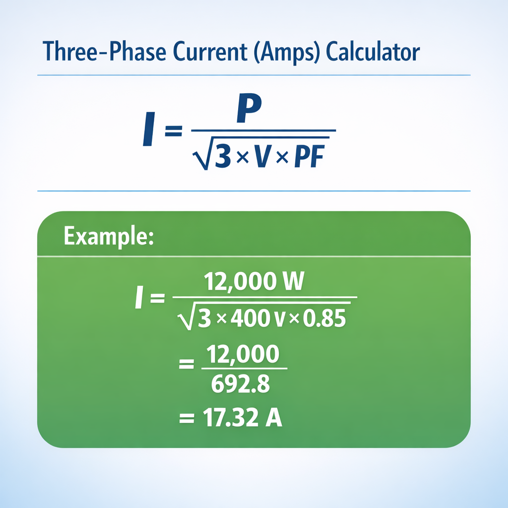
The three-phase current calculator on this page converts kW, HP, or kVA into line current (amps) for any three-phase AC system. Knowing the exact amperage is essential for sizing breakers, selecting cable gauges, setting motor overload relays, and verifying that your transformer or generator is not overloaded. The core formula — I = P × 1,000 ÷ (V × √3 × PF) — applies to every standard three-phase voltage (208, 380, 400, 415, 440, 480, 600 V), and this guide walks you through it with real-world examples at each voltage level.
Whether you are a plant electrician sizing a feeder for a new 50 HP motor, a consulting engineer calculating the load on a 480 V MCC, or a maintenance technician checking nameplate amps against clamp-meter readings, this page gives you the formulas, reference tables, and professional context you need. All calculations follow IEEE, NEMA MG 1, and IEC 60034 motor rating standards.
Three-Phase Motor Full-Load Amps Table
The table below lists standard motor ratings (HP and kW) with their approximate full-load amps (FLA) at common three-phase voltages. These values are based on NEMA MG 1 Table 12.2 and typical motor efficiencies and power factors. Always verify against the specific motor nameplate before sizing protection and conductors.
| HP | kW | FLA @ 208V | FLA @ 380V | FLA @ 415V | FLA @ 480V |
|---|---|---|---|---|---|
| 1 | 0.75 | 3.5 | 1.9 | 1.8 | 1.5 |
| 2 | 1.5 | 6.8 | 3.7 | 3.4 | 2.9 |
| 3 | 2.2 | 9.6 | 5.3 | 4.8 | 4.2 |
| 5 | 3.7 | 15.2 | 8.3 | 7.6 | 6.6 |
| 7.5 | 5.5 | 22 | 12.1 | 11.0 | 9.6 |
| 10 | 7.5 | 28 | 15.4 | 14.0 | 12.2 |
| 15 | 11 | 42 | 23.0 | 21.0 | 18.2 |
| 20 | 15 | 54 | 29.6 | 27.1 | 23.4 |
| 25 | 18.6 | 68 | 37.3 | 34.1 | 29.5 |
| 30 | 22 | 80 | 43.9 | 40.1 | 34.7 |
| 40 | 30 | 104 | 57.0 | 52.1 | 45.1 |
| 50 | 37 | 130 | 71.3 | 65.1 | 56.3 |
| 75 | 55 | 192 | 105.3 | 96.3 | 83.3 |
| 100 | 75 | 248 | 136.0 | 124.3 | 107.6 |
| 150 | 110 | 360 | 197.5 | 180.5 | 156.2 |
| 200 | 150 | 480 | 263.3 | 240.7 | 208.3 |
Note: FLA values are approximate and assume typical PF (0.85–0.87) and efficiency (0.89–0.94) for TEFC induction motors. The actual nameplate amps may differ by ±10%. For code-compliant wire sizing, always use NEC Table 430.250 or the motor nameplate — whichever is larger.
Three-Phase Current Formulas Step by Step
There are three primary formulas for calculating three-phase current, depending on whether your starting point is kW, HP, or kVA.
From kW (kilowatts)
This is the most common formula in industrial load calculations. You need the real power in kW, the line-to-line voltage, and the power factor. The √3 factor (≈ 1.732) accounts for three-phase power delivery.
From HP (horsepower)
For motor loads rated in horsepower. The factor 746 converts HP to watts (1 HP = 746 W). The additional variable η (eta) is the motor efficiency — you need it because the motor draws more electrical power than its shaft output. Typical values range from 0.85 for small motors to 0.96 for premium-efficiency large motors.
From kVA (kilovolt-amps)
For transformer and generator nameplate ratings. No power factor is needed because kVA already represents apparent power (the full current product). This formula is the simplest of the three.
Step-by-step: Calculate amps for a 15 kW load at 480 V, PF 0.85
- Identify values: kW = 15, V = 480, PF = 0.85.
- Apply formula: I = 15 × 1,000 ÷ (480 × 1.732 × 0.85).
- Calculate denominator: 480 × 1.732 = 831.36 → 831.36 × 0.85 = 706.66.
- Calculate current: 15,000 ÷ 706.66 = 21.23 A.
- Context: 21.23 A is consistent with a 20 HP motor at full load on a 480 V system — correct.
kW vs. HP vs. kVA — Which Formula to Use
| Starting Unit | Formula | PF Needed? | η Needed? | When to Use |
|---|---|---|---|---|
| kW | I = kW × 1,000 ÷ (V × √3 × PF) | Yes | No | Load schedules, energy meters, VFD ratings |
| HP | I = HP × 746 ÷ (V × √3 × PF × η) | Yes | Yes | Motor nameplates (NEMA rated) |
| kVA | I = kVA × 1,000 ÷ (V × √3) | No | No | Transformer / generator nameplates |
The key difference: kW and HP represent real power (what does useful work), so you need the power factor to find the total current. kVA represents apparent power (the full V × A product), so the power factor is already baked in. If you are sizing a breaker or cable, use the formula that matches the nameplate data you have — do not mix kW with the kVA formula or you will undersize your conductors.
Amps to kW / HP — Inverse Calculation
To go the other direction — from measured amps to power — rearrange the formulas:
| Voltage | Amps | PF | kW | ≈ HP |
|---|---|---|---|---|
| 208 | 28 | 0.85 | 8.57 | 11.5 |
| 380 | 30 | 0.85 | 16.78 | 22.5 |
| 415 | 30 | 0.85 | 18.34 | 24.6 |
| 480 | 65 | 0.87 | 47.00 | 63.0 |
| 480 | 124 | 0.86 | 88.62 | 118.8 |
For more detail on the amps-to-kW direction, use our Amps to kW Calculator. And to convert amps directly to horsepower, try the Amps to HP Calculator.
6 Solved Examples — Real-World 3-Phase Amp Calculations
Example 1 — 15 kW Motor at 480 V
Data: P = 15 kW, V = 480 V, PF = 0.86.
Formula: I = kW × 1,000 ÷ (V × √3 × PF)
Calculation: 15,000 ÷ (480 × 1.732 × 0.86) = 15,000 ÷ 714.50 = 20.99 A
≈ 21 A — consistent with a 20 HP motor FLA. NEC requires a minimum conductor ampacity of 21 × 1.25 = 26.25 A for continuous loads, so #10 AWG copper (30 A at 75°C) is the minimum acceptable wire size.
Example 2 — 50 HP Motor at 415 V
Data: P = 50 HP, V = 415 V, PF = 0.85, η = 0.91.
Formula: I = HP × 746 ÷ (V × √3 × PF × η)
Calculation: 37,300 ÷ (415 × 1.732 × 0.85 × 0.91) = 37,300 ÷ 556.17 = 67.07 A
67 A at 415 V for a 50 HP motor. The breaker should be sized per NEC 430.52 — typically 250% of FLA for inverse-time breakers: 67 × 2.5 = 167.5 A → select a 175 A breaker.
Example 3 — 100 kVA Transformer at 480 V
Data: S = 100 kVA, V = 480 V.
Formula: I = kVA × 1,000 ÷ (V × √3)
Calculation: 100,000 ÷ (480 × 1.732) = 100,000 ÷ 831.36 = 120.28 A
120.28 A is the rated full-load secondary current of a 100 kVA, 480 V three-phase transformer. This value determines the secondary breaker size and feeder conductor gauge.
Example 4 — 22 kW Compressor at 380 V
Data: P = 22 kW, V = 380 V, PF = 0.85.
Formula: I = kW × 1,000 ÷ (V × √3 × PF)
Calculation: 22,000 ÷ (380 × 1.732 × 0.85) = 22,000 ÷ 559.19 = 39.34 A
39.34 A for a 22 kW (30 HP) screw compressor at 380 V. The cable must handle at least 39.34 × 1.25 = 49.18 A continuously. Select 10 mm² copper (IEC rating ≈ 57 A) or #6 AWG (55 A at 75°C per NEC).
Example 5 — 7.5 HP Motor at 208 V
Data: P = 7.5 HP, V = 208 V, PF = 0.82, η = 0.88.
Formula: I = HP × 746 ÷ (V × √3 × PF × η)
Calculation: 5,595 ÷ (208 × 1.732 × 0.82 × 0.88) = 5,595 ÷ 259.86 = 21.53 A
21.53 A at 208 V. Note how the same HP draws significantly more amps at 208 V than at 480 V — this is why industrial plants prefer higher voltages for motors above 5 HP: lower current means smaller cables, breakers, and lower I²R losses.
Example 6 — 75 kW VFD-Driven Motor at 400 V
Data: P = 75 kW, V = 400 V, PF = 0.95 (VFD output).
Formula: I = kW × 1,000 ÷ (V × √3 × PF)
Calculation: 75,000 ÷ (400 × 1.732 × 0.95) = 75,000 ÷ 658.16 = 113.95 A
113.95 A on the VFD output side at 400 V. VFDs improve the displacement PF to near unity (0.95–0.99), so the current is lower than it would be for the same motor on direct-online start with PF 0.85. On the VFD input side, the current may differ due to harmonic content.
Where You Need the 3-Phase Current Calculation
Breaker and cable sizing
Every circuit breaker and conductor must be rated above the calculated full-load amps. NEC Article 430 requires motor branch circuit conductors to carry at least 125% of the motor FLA. Knowing the exact amps from the three-phase formula is the first step in any wire-sizing exercise. For conductor gauge conversions, see our AWG to mm² equivalences page.
Motor overload relay settings
Overload relays (heaters) in motor starters are set to the motor’s FLA. If you do not have the nameplate, calculate amps from HP or kW using the formulas above. Set the overload at 115% of FLA (or 125% for motors with a 1.15 service factor per NEC 430.32).
Transformer and generator load verification
Measure the current on each phase with a clamp meter, then compare against the calculated full-load amps from the kVA formula. If measured amps exceed 80% of the transformer’s rated FLA on a continuous basis, the transformer is approaching its thermal limit and you should consider adding capacity. For more on this topic, try our Transformer kVA Sizing Calculator.
Load balancing across phases
Three-phase loads should be balanced so each phase carries roughly the same current. Unbalanced loads cause neutral overloads, negative-sequence currents that overheat motors, and uneven voltage drops. Calculate the amps per phase for each load, then distribute them evenly across A, B, and C. See our Balanced and Unbalanced Load Calculation guide for the full method.
Quick Equivalences
3-Phase Current Formula
I = kW × 1,000 ÷ (V × √3 × PF)
The primary formula for calculating three-phase line current from real power. Works at any voltage.
3-Phase Amp Calculator
Use the tool above
Enter kW, HP, or kVA plus voltage and PF. The result updates instantly for 208, 380, 400, 415, 440, 480, or 600 V.
kW to Amps 3-Phase
I = kW × 1,000 ÷ (V × 1.732 × PF)
Example: 15 kW at 480 V, PF 0.85 → 15,000 ÷ (480 × 1.732 × 0.85) = 21.23 A.
3-Phase Motor Amps Calculation
I = HP × 746 ÷ (V × √3 × PF × η)
Use this when the nameplate shows HP. Include motor efficiency (η). A 50 HP motor at 480 V draws roughly 65 A.
Amperage Calculator 3-Phase
Same as 3-phase amp calculator
“Amperage” and “amps” refer to the same quantity — current measured in amperes. The formulas are identical.
3-Phase Load Calculator
Calculate amps per phase, then sum
For a full panel load schedule, calculate the amps for each load and add them. Consider demand factors per NEC Article 220.
Three-Phase Current Calculation
I = P ÷ (V × √3 × PF)
Generic form. P is in watts (not kW) when you omit the × 1,000 factor. Make sure your units are consistent.
Calculating 3-Phase Amps
Divide power by (V × √3 × PF)
The √3 factor is always present in three-phase formulas. For single-phase, remove √3 and use I = P ÷ (V × PF).
FAQ — Three-Phase Current Calculation
What is the formula for three-phase current?
I = kW × 1,000 ÷ (V × √3 × PF). Divide the power in watts by the product of line voltage, √3 (1.732), and the power factor. Example: 22 kW at 380 V, PF 0.85 → 22,000 ÷ (380 × 1.732 × 0.85) = 39.34 A.
Why is √3 used in three-phase calculations?
√3 (≈ 1.732) arises from the 120° phase displacement between three AC phases. It converts line-to-line voltage and line current into total three-phase power. Without it, you would underestimate the power by about 42%.
How do I calculate amps from HP for a three-phase motor?
Use I = HP × 746 ÷ (V × √3 × PF × η). Include the motor efficiency (η) because HP is shaft output, not electrical input. A 50 HP motor at 480 V with PF 0.85 and η 0.91: 37,300 ÷ (480 × 1.732 × 0.85 × 0.91) = 56.3 A.
What is a typical power factor for a three-phase motor?
0.80–0.90 at full load for standard induction motors. At partial load (e.g., 50% load), PF drops to 0.65–0.75. Premium-efficiency motors may reach 0.88–0.92. Motors with VFDs typically show displacement PF of 0.95–0.99 on the output side.
How many amps does a 100 HP motor draw at 480 V?
Approximately 124 A at full load per NEC Table 430.250. Calculated: 100 × 746 ÷ (480 × 1.732 × 0.86 × 0.93) = 74,600 ÷ 664.55 ≈ 112 A. The NEC table value (124 A) is slightly conservative and is the one used for code-compliant sizing.
What is the difference between line current and phase current?
In a wye (Y) connection, line current equals phase current. In a delta (Δ) connection, line current is √3 times the phase current. The three-phase power formula always uses line current and line-to-line voltage, regardless of the winding connection.
Can I use the same formula for 208 V and 480 V?
Yes. The formula I = kW × 1,000 ÷ (V × √3 × PF) works at any three-phase voltage. Just plug in the correct line-to-line voltage. At 208 V the current will be roughly 2.3× higher than at 480 V for the same kW load — that is why 480 V is preferred for large loads.
How do I calculate three-phase amps from kVA?
I = kVA × 1,000 ÷ (V × √3). No power factor needed. Example: 75 kVA transformer at 480 V → 75,000 ÷ (480 × 1.732) = 75,000 ÷ 831.36 = 90.21 A.
What happens if I use single-phase formula for a three-phase load?
You will get the wrong answer. The single-phase formula I = P ÷ (V × PF) is missing the √3 factor. For a 15 kW, 480 V, PF 0.85 load: single-phase formula gives 36.76 A; three-phase formula gives 21.23 A. Using the wrong formula could lead to significantly oversized or undersized cables.
How do I size a breaker from calculated amps?
For motor branch circuits, NEC 430.52 allows up to 250% of FLA for inverse-time breakers (e.g., 21 A × 2.5 = 52.5 A → 50 A breaker). For non-motor continuous loads, NEC 210.20 requires the breaker to be at least 125% of FLA (21 A × 1.25 = 26.25 A → 30 A breaker). Always follow the applicable code for your jurisdiction.
What motor efficiency should I use if it is not on the nameplate?
Use NEMA premium efficiency defaults: 0.85–0.87 for 1–5 HP, 0.89–0.91 for 7.5–25 HP, 0.92–0.94 for 30–100 HP, and 0.95–0.96 for 125+ HP. These are conservative estimates per NEMA MG 1 Table 12.12. If the motor is old or rewound, actual efficiency may be 2–5 percentage points lower.
Does frequency (50 Hz vs. 60 Hz) affect the current calculation?
Not directly in the I = kW ÷ (V × √3 × PF) formula — frequency does not appear. However, frequency affects the motor’s speed, slip, efficiency, and power factor, which in turn affect the current. A 50 Hz motor running at 60 Hz (or vice versa) will have different characteristics than its nameplate values. Always use the values that match the actual operating frequency.
Related Calculators
- Amps to kW Calculator
- Amps to Watts Calculator
- Amps to VA Calculator
- Amps to HP Calculator
- Motor Efficiency Calculator
- Balanced and Unbalanced Load Calculation