This technical guide explains converting volts, amps, and watts for DC and AC power systems.
This covers accurate formulas, practical examples, standards, and selection guidance for engineers.
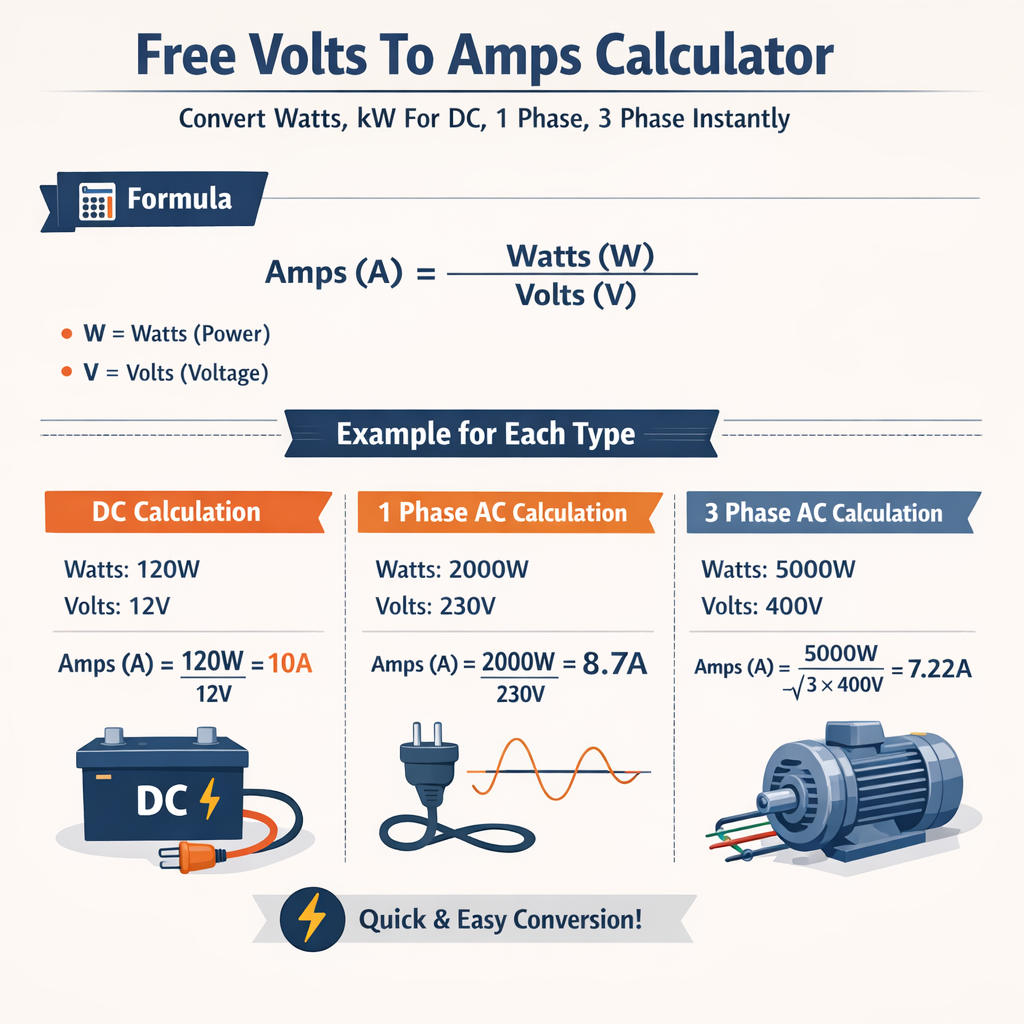
Volts to Amps Calculator (DC, 1‑Phase, 3‑Phase) from Watts / kW
Fundamental electrical relationships for volts, amps, and watts
Understanding the algebraic and vector relationships among voltage, current, power, and power factor is essential for accurate conversions and engineering design. The following core relationships are the basis for both DC and AC single- and three-phase calculations.
Basic DC relationship
Power, voltage and current in a direct current (DC) circuit are linearly related by:
Where:
- P is power in watts (W)
- V is voltage in volts (V)
- I is current in amperes (A)
Typical values: V = 12 V (low-voltage battery), 48 V (telecom), 380 V (high-voltage DC distribution for some applications), P typical loads 10 W to several kW.
Single-phase AC (resistive or power-factor-corrected)
For single-phase alternating current where power factor (pf) may differ from unity:
Where:
- P is real power in watts (W)
- V is RMS line-to-neutral voltage (V)
- I is RMS current (A)
- pf is power factor (dimensionless, 0–1)
Typical mains: 120 V, 230 V, 240 V; typical pf for resistive loads ≈ 1.0, for motors 0.7–0.95.
Three-phase AC (balanced load)
For balanced three-phase systems the relationship depends on whether voltages given are line-to-line or line-to-neutral and whether the connection is star (wye) or delta:
Where:
- P is total real power (W)
- V_LL is line-to-line RMS voltage (V)
- I_L is line current (A)
- pf is power factor (dimensionless)
Alternatively, if V_LN is line-to-neutral RMS voltage for each phase and the system is three-phase balanced:
Typical industrial voltages: 400 V, 415 V, 480 V (line-to-line). Typical pf for motors and industrial loads: 0.8–0.95.
Conversion formulas and their algebraic rearrangements
To convert among volts, amps and watts use algebraic rearrangement of the core relationships. The following are the most used forms for instant conversions.
DC conversion formulas
Given any two variables you can find the third:
Example typical values: P = 500 W, V = 48 V → I = 500 / 48 = 10.417 A.
Single-phase AC conversion formulas
For single-phase AC with known pf:
Typical pf values used for conservative design: 0.8 for unknown loads, 0.9–0.95 for industrial corrected systems.
Three-phase AC conversion formulas
For balanced three-phase line-to-line voltage V_LL:
Note: √3 is approximately 1.732. Use phase relationships for delta connected motors if specified differently.
Variable definitions, units, and typical engineering values
Precise definitions and typical ranges ensure correct unit handling and accurate design margins in calculations.
- P — Active (real) power in watts (W). Often expressed in kilowatts (kW) where 1 kW = 1000 W.
- V — RMS voltage in volts (V). For DC use steady state Vdc.
- I — RMS current in amperes (A) or instantaneous DC current for DC circuits.
- pf — Power factor (cos φ) dimensionless. pf ≤ 1 commonly 0.6–1.0 depending on load.
- √3 — Conversion factor for three-phase: 1.73205 (approx).
Typical engineering values and selection guidance:
- Design derating: continuous loads use 125% factor for conductor and protective device sizing per many codes.
- Temperature correction: consider conductor ampacity reduction at high ambient temperatures.
- Inrush currents: motors and capacitive loads can have transient inrush several times steady‑state current; use motor starting rules for short‑time behavior.
Extensive reference tables with common system voltages and currents
| System | Typical Voltage | Example Load Power (kW) | Calculated Current (A) single‑phase (pf=1) | Calculated Current (A) three‑phase (pf=0.9) |
|---|---|---|---|---|
| Residential (US) | 120 V | 1.5 kW | 12.5 A | N/A |
| Residential (EU) | 230 V | 3.0 kW | 13.04 A | N/A |
| Small industrial single-phase | 230 V | 10 kW | 43.48 A | N/A |
| Industrial three-phase | 400 V (LL) | 15 kW | N/A | 24.05 A |
| Industrial high power | 480 V (LL) | 50 kW | N/A | 60.09 A |
| Telecom DC | 48 V DC | 1 kW | 20.83 A | N/A |
| Battery EV traction | 400 V DC nominal | 75 kW | 187.5 A | N/A |
| Motor Rating | Voltage (V) | Power (kW) | Line Current (A) 3-φ (pf=0.85) | Recommended Circuit Breaker (A) |
|---|---|---|---|---|
| Small motor | 400 V | 3.0 | 6.4 | 10 |
| Medium motor | 400 V | 11.0 | 25.3 | 35 |
| Large motor | 400 V | 37.0 | 85.5 | 125 |
| Very large motor | 480 V | 150.0 | 181.3 | 300 |
Practical calculation examples with full development
Example 1 — DC system: Convert volts to amps for a battery powered load
Problem statement: A telecom rectifier supplies 1200 W to equipment from a 48 V DC bus. Determine the DC current and select a fuse rating assuming continuous operation with 125% derating.
Step 1: Use P = V × I ⇒ I = P / V.
Step 2: Apply continuous load derating for protective device sizing. Standard engineering practice uses 125% for continuous loads.
Select commercially available protective device: next standard size = 32 A fuse or 40 A breaker depending on time‑current characteristics and manufacturer. Verify fuse characteristics for DC interruption capability at 48 V.
Notes:
- Check cable ampacity for 25 A continuous at installation ambient temperature.
- Consider DC load break requirements (not all breakers have DC ratings; prefer DC-rated fuses or switches).
Example 2 — Single-phase AC: Convert watts to amps for residential heater
Problem statement: A resistive electric heater rated 3.6 kW is connected to a 230 V single-phase supply. Determine steady-state current and recommended circuit breaker rating.
Assume pf = 1 (resistive).
Select nearest standard breaker: 20 A or 25 A. For continuous resistive load consider using a 25 A breaker with appropriate conductor (e.g., 2.5 mm² copper often rated for 20–25 A depending on installation; check local codes).
Step 3: Conductor sizing: Use cable ampacity tables (account for ambient temperature and grouping). For example, 2.5 mm² copper at 30°C typical rating 24–27 A — acceptable for 20 A protection but may be marginal for 25 A in some installations. When in doubt, use 4 mm² for margin.
Example 3 — Three-phase AC: Convert kilowatts to line current for motor selection and protection
Problem statement: A three-phase induction motor rated 22 kW is connected to a 400 V line-to-line supply. Motor nameplate power factor is 0.88. Determine the line current and a recommended starter/breaker rating using a 125% continuous derating.
Step 1: Use the three-phase formula I = P / (√3 × V_LL × pf).
Step 2: Apply derating for continuous load equipment sizing (where applicable): Circuit rating = 36.07 × 1.25 = 45.09 A
Select breaker/starter rating: next standard size 50 A.
Step 3: Check motor starting current: Inrush may be 5–7× full-load current. For design, use manufacturer locked-rotor current to size protection and consider reduced-voltage starter or soft starter if required to limit supply disturbance.
Step 4: Conductor sizing: Select conductor with ampacity >36.07 A and compatible with chosen protective device and ambient conditions. Typical selection: 6 mm² copper has ~34–38 A depending on standard tables; 10 mm² provides comfortable margin in many tables. Verify with local standards.
Advanced topics: power factor correction, effective kilowatt conversion, and instantaneous power
Power factor impact — active, reactive and apparent power
Definitions:
- Apparent power S (VA) = V × I (single-phase) or S = √3 × V_LL × I (three-phase).
- Real (active) power P (W) = S × pf.
- Reactive power Q (VAR) = S × sin φ, where cos φ = pf.
Formulas in HTML-only notation:
Typical engineering considerations:
- Improve pf to near unity to reduce apparent power and lower current, enabling use of smaller conductors and reducing utility penalties.
- Sizing of capacitors must consider resonance and harmonic distortion; harmonics require detuned filters per standards (IEEE 519 guidance).
Instantaneous conversions and transient considerations
Instantaneous power computations for time-varying signals use instantaneous voltage v(t) and current i(t):
For practical power quality and harmonic analysis, use RMS values and Fourier analysis; instantaneous peak currents are important for thermal stress on conductors and protective device coordination.
Standards, normative references and authoritative resources
Relevant standards and authoritative guidance for volts, amps, watts conversion and electrical installations:
- IEC 60038 — Voltages for mains systems: sets standard nominal voltages: https://www.iec.ch
- IEC 60909 — Short‑circuit current calculation in three‑phase AC systems: https://www.iec.ch/standards
- IEEE Std 141 (Red Book) — Power distribution design practices: https://www.ieee.org
- IEEE Std 142 (Green Book) — Grounding of industrial and commercial power systems: https://www.ieee.org
- NFPA 70 (NEC) — National Electrical Code (USA): conductor sizing and overcurrent protection: https://www.nfpa.org/NEC
- IEC 61000 series and IEEE 519 — Power quality and harmonic limits: https://www.iec.ch and https://standards.ieee.org
- NEMA MG1 — Motors and generators guidelines for nameplate data and starting currents: https://www.nema.org
When designing or verifying installations, consult the local adopted edition of these standards and the manufacturer’s data sheets for precise thermal, short‑circuit and transient characteristics.
Practical engineering checklist for conversions and system sizing
Follow this checklist to ensure conversions are accurate and designs are compliant:
- Verify whether voltage provided is RMS (AC) or DC nominal.
- Identify power type: real (W), apparent (VA), or reactive (VAR).
- Confirm power factor for AC loads; assume conservative pf if unknown (e.g., 0.8).
- For three-phase calculations ensure use of line‑to‑line voltage in formula with √3 factor.
- Apply continuous load derating (commonly 125%) when sizing conductors and protective devices per applicable codes.
- Account for inrush currents and short time thermal capacity of protective devices.
- Consult standards (IEC, IEEE, NEC) for conductor ampacity tables, derating factors, and protective device coordination.
Common pitfalls and troubleshooting during conversions
- Mixing peak and RMS values in AC: always use RMS for power and current unless explicitly calculating instantaneous or peak values.
- Neglecting power factor: underestimation of current for inductive/capacitive loads leads to undersized wiring.
- Confusing line-to-line and line-to-neutral voltages in three-phase systems causing factor of √3 errors.
- Ignoring ambient temperature and grouping deratings: ampacity reductions can lead to overheating if unaccounted.
- Assuming nameplate currents are continuous ratings: nameplate often indicates rated (continuous) current but verify duty cycle.
Appendix — Quick reference formulas and constants
Core formulas for quick copy-and-paste (operators must ensure units):
- DC: P = V × I
- DC: I = P / V
- Single-phase AC: P = V × I × pf
- Single-phase AC: I = P / (V × pf)
- Three-phase AC: P = √3 × V_LL × I × pf
- Three-phase AC: I = P / (√3 × V_LL × pf)
- √3 ≈ 1.732
- 1 kW = 1000 W; 1 MW = 1,000,000 W
Further reading and online calculators
For verification and quick checks engineers commonly use vendor or standards-based calculators; ensure inputs match the chosen formula (single-phase vs three-phase, DC vs AC). Trusted sources with technical calculators and guidance:
- IEC standards catalog: https://www.iec.ch
- IEEE standards and educational resources: https://www.ieee.org
- NFPA and NEC compliance guides: https://www.nfpa.org
- Manufacturer datasheets (e.g., motor or transformer OEM) for accurate nameplate and inrush data
Summary of engineering best practices
Converting volts to amps and watts across DC, single-phase and three-phase systems is a deterministic algebraic process but requires careful attention to power factor, RMS vs DC values, derating, and local standards. Use the formulas in this document, confirm variables with measured or nameplate data, and always cross‑check conductor and protective device selections against applicable codes and manufacturers’ ratings.
Regulatory citations and authority verification
Reference the following documents for regulatory compliance, exact conductor tables, and protective device selection:
- IEC 60038 — Standard voltages
- IEC 60909 — Short-circuit calculations
- IEEE Std 141 and IEEE Std 142 — System design and grounding
- NFPA 70 (NEC) — US installation rules
- IEEE 519 — Harmonic control and limits
If you need worked examples for a specific voltage, power factor, or installation standard (e.g., NEC ampacity tables for chosen conductor and ambient conditions), provide the system parameters and I will calculate currents, protection sizes, and recommended conductor gauge compliant with the selected code.