Accurate three-phase motor current calculation prevents overloads, optimizes protection, and ensures efficient power distribution reliability.
Engineers require robust calculators offering selectable connection types, power factors, efficiencies, and ambient temperature corrections.
Three-Phase Motor Current Calculator — Essential Tool
Why precise three-phase motor current calculation matters for electrical systems
Accurate current estimation is foundational for selecting conductors, protective devices, starters, and for assessing thermal and mechanical stresses. Underestimating current leads to tripping, overheating, and reduced equipment life; overestimating increases capital and operational costs. A robust calculator reduces iteration time and enforces consistent engineering rules across multi-discipline teams.This article treats the theoretical basis, practical corrections, normative references, and the functional specification of a "must-have" three-phase motor current calculator. It includes explicit formulas (expressed in plain HTML), comprehensive tables of common motor data, and two fully worked real-world examples demonstrating implementation details and decision-making flow.Fundamental power-to-current relationships for three-phase motors
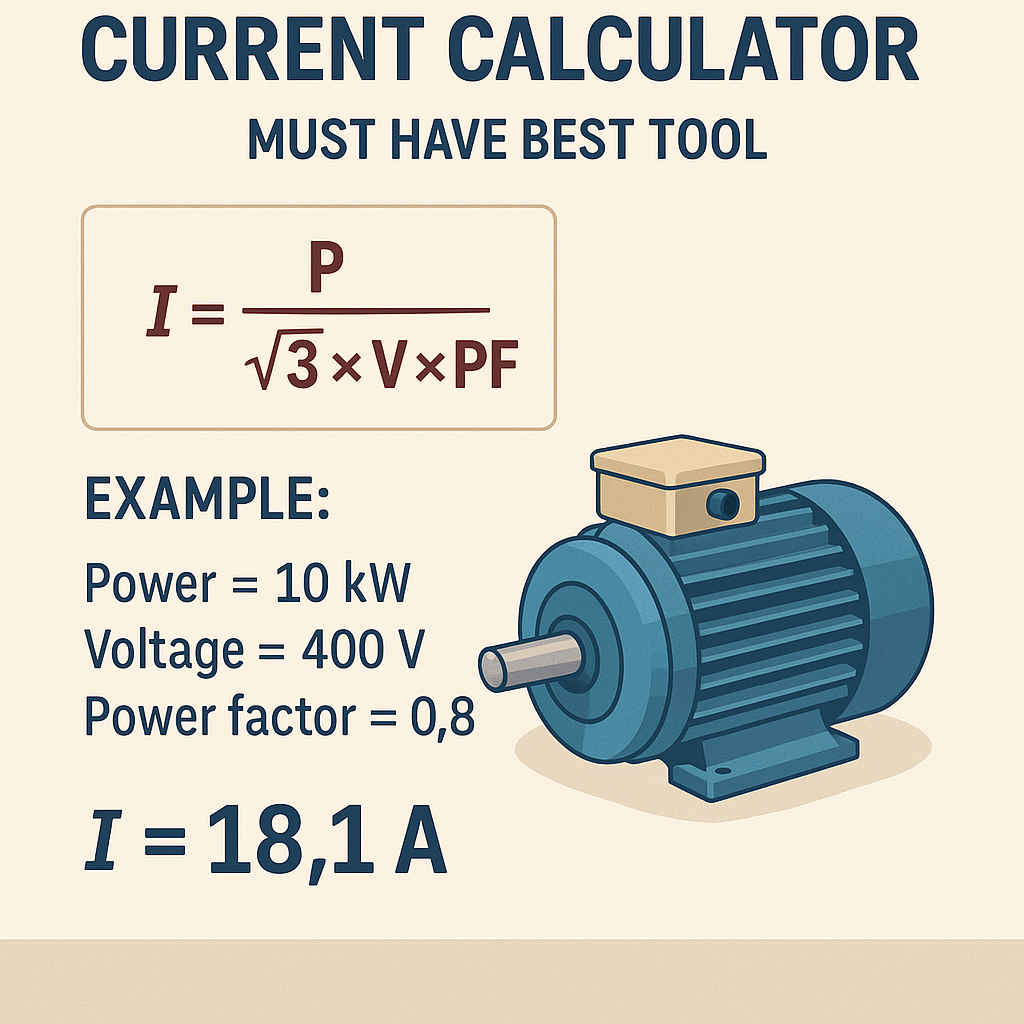
For a balanced three-phase motor supplied with line-to-line voltage V_L (also called line voltage), the steady-state line current I_L for mechanical output power P_out is given by:I_L = P_out / (sqrt(3) × V_L × PF × η)
- P_out is the motor mechanical output power (Watts).
- sqrt(3) = 1.7320508075688772 (ratio for three-phase systems).
- V_L is line-to-line voltage (Volts).
- PF is power factor (unitless, typically 0.7–0.95 for motors under load).
- η is motor efficiency (decimal, e.g., 0.90 for 90%).
P_out (W) = HP × 745.699872
- If P_out is specified as input electrical power P_in, replace P_out with P_in and set PF and η consistently (P_in = P_out / η).
- The formula yields the steady-state full-load line current for balanced loads. Unbalanced phases require per-phase calculation.
Phase connection specifics (Wye vs Delta)
Most motor nameplates specify line voltage V_L; the I_L calculated above is the line current for the motor regardless of connection type when using the motor rated line voltage and rated power. For clarity:- Wye (Y): Phase voltage V_ph = V_L / sqrt(3). Phase current I_ph = I_L.
- Delta (Δ): Phase voltage V_ph = V_L. Line current I_L = sqrt(3) × I_ph.
Detailed variable explanations and typical values
Formula recap: I_L = P_out / (sqrt(3) × V_L × PF × η)
- P_out (motor rated mechanical output): typically 0.37 kW (0.5 HP) to several MW for industrial motors.
- V_L (line voltage): common industrial values—230 V, 400 V, 415 V, 460 V, 480 V, 600 V, 690 V. Use nominal system voltage.
- PF (power factor): small motors at light load 0.6–0.8; full load 0.85–0.95. Asynchronous motors usually 0.8–0.9 at full load.
- η (efficiency): IE2/IE3/IE4 classes; typical full-load efficiencies: small motors 75–85%, medium 88–95%, high-efficiency >95%.
- Starting current (inrush): 4–8 × full-load current for direct-on-line (DOL) starting; reduced with soft-start or VFD.
- Locked-rotor current (LRA): nameplate or manufacturer datum; often 5–10 × full-load current.
Correction factors and derating considerations
Accurate motor current calculators must include correction factors for:- Ambient temperature and conductor ampacity derating (for conductor sizing calculations).
- Altitude (affecting cooling and hence permissible current or derating for equipment).
- Duty cycle and intermittent loading (influence thermal capacity and sizing).
- Harmonics (non-sinusoidal supply increases heating and effective RMS current).
I_corrected = I_L × K_temp × K_alt × K_harmonics
- K_temp ≈ 1.0 to 1.15 depending on difference from 30 °C reference ampacity tables.
- K_alt adjusts for altitude: for example, a conservative multiplier of 1.05–1.20 above 1000 m depending on equipment standards.
- K_harmonics depends on total harmonic distortion (THD) and equipment design—consult IEC/IEEE harmonics standards.
Tables — typical full-load currents for common motor sizes and voltages
| Motor Power (kW) | Motor Power (HP) | FL Current @ 230 V 3φ (A) | FL Current @ 400 V 3φ (A) | FL Current @ 460 V 3φ (A) | FL Current @ 690 V 3φ (A) |
|---|---|---|---|---|---|
| 0.37 | 0.5 | 1.3 | 0.75 | 0.65 | 0.45 |
| 0.75 | 1 | 2.7 | 1.6 | 1.4 | 0.98 |
| 1.5 | 2 | 5.4 | 3.1 | 2.8 | 1.96 |
| 3.0 | 4 | 10.8 | 6.1 | 5.6 | 3.9 |
| 7.5 | 10 | 27.2 | 15.3 | 14.1 | 9.8 |
| 11 | 15 | 39.9 | 22.4 | 20.7 | 14.3 |
| 18.5 | 25 | 67.1 | 37.7 | 34.9 | 24.0 |
| 37 | 50 | 134.1 | 75.2 | 69.7 | 47.9 |
| 55 | 75 | 199.7 | 112.0 | 103.8 | 71.3 |
| 75 | 100 | 272.4 | 152.8 | 141.6 | 97.3 |
| 110 | 150 | 399.4 | 224.0 | 207.6 | 142.7 |
- Values are illustrative approximations using typical PF and η—consult motor nameplate or manufacturer for exact values.
- Tables are useful for quick checks; a calculator should accept actual PF and η for accuracy.
| Parameter | Small motors (< 1 kW) | Medium (1–75 kW) | Large (> 75 kW) |
|---|---|---|---|
| Typical PF at FL | 0.6–0.80 | 0.75–0.90 | 0.85–0.95 |
| Typical Efficiency η | 70–85% | 85–95% | 90–97% |
| Starting multiplier (DOL) | 4–6 × I_FL | 5–7 × I_FL | 6–10 × I_FL |
| Typical Service Factor | 1.0–1.15 | 1.0–1.15 | 1.0–1.15 |
| Common frame sizes | IEC 63–90 | IEC 100–225 | IEC 250+ |
Designing a must-have three-phase motor current calculator — features and UX
A best-in-class tool should be engineered for clarity, traceability, and compliance. Core features:- Input modes: power (kW/HP), current (A), torque (Nm), or nameplate direct inputs.
- Voltage selection: common nominal supply voltages with tolerance options (±x%).
- Connection type: selectable Wye or Delta with internal conversion logic.
- Efficiency and power factor: editable inputs and selection from standards-based default tables (IE code classes).
- Start mode: DOL, star-delta, soft starter, VFD (with configurable starting current multipliers).
- Correction factors: ambient temperature, altitude, cable grouping, harmonics (THD), and duty cycle.
- Outputs: full-load current, locked-rotor/inrush current estimate, required conductor ampacity, suggested circuit breaker / fuse sizes (with normative compliance notes).
- Traceability: calculation log and PDF export showing every formula and chosen standard references.
- International standards mapping: toggles to format outputs for IEC or NEC conventions (informational only).
- Use clear units, automatic conversion between kW/HP and user-selected voltage systems.
- Provide sensible defaults but require confirmation of PF and η for critical projects.
- Include warnings when results exceed typical inrush limits, or when conductor sizing must consider thermal capacities.
- Offer API endpoints for integration with CAD or grid studies.
Formulas and calculation flow for an integrated tool
Primary flow:- Normalize inputs to base units: P_out (W), V_L (V).
- Compute I_FL:I_FL = P_out / (sqrt(3) × V_L × PF × η)
- Estimate starting/inrush current:where SF_starting is a selected starting factor (e.g., 6 for DOL).I_start_est = I_FL × SF_starting
- Apply correction multipliers for ambient/altitude/harmonics:
- Derive conductor minimum ampacity (A_cable_min) using the corrected current and safety margin:
- Select protection device nominal rating consistent with normative rules and inrush considerations.
I_adj = I_FL × K_temp × K_alt × K_harmonics
A_cable_min = I_adj × Safety_factor_for_continuous_service
- Safety_factor_for_continuous_service: 1.0–1.25 depending on code and duty cycle.
- Fuse/CB selection: device must tolerate inrush without nuisance trip—select device with appropriate inrush rating or time-delay.
Normative standards and authoritative references
Key standards to reference and implement guidance from:- IEC 60034: Rotating electrical machines — motor performance, efficiencies, and nameplate data. Link: https://www.iec.ch
- IEC 60364 / IEC 60204: Electrical installation rules affecting conductor sizing and protection selection. Link: https://www.iec.ch
- NEMA MG1: Motors and generators — U.S. industry standard for motor ratings and tests. Link: https://www.nema.org
- NFPA 70 (NEC): National Electrical Code — for conductor sizing, short-circuit, and overcurrent protection in the U.S. Link: https://www.nfpa.org
- IEEE Std 519: Recommended practices and requirements for harmonic control in electrical power systems — important for VFD-fed motors. Link: https://www.ieee.org
Real-world example 1 — Medium industrial motor at 400 V
Scenario:- Motor rated output: 15 kW
- Supply: 400 V three-phase
- Power factor PF (assumed at full load): 0.88
- Efficiency η (IE3 motor full-load): 0.93
- Starting method: Direct-On-Line (DOL), starting multiplier = 6
- Ambient temperature: 40 °C (conductors derated via K_temp = 1.08 for ampacity)
- Altitude: negligible (assume K_alt = 1.00)
P_out = 15 kW = 15,000 W
I_FL = P_out / (sqrt(3) × V_L × PF × η)
I_FL = 15,000 / (1.73205 × 400 × 0.88 × 0.93)
- 1.73205 × 400 = 692.82
- 692.82 × 0.88 = 609.68
- 609.68 × 0.93 = 567.00 (approx)
I_FL ≈ 15,000 / 567.00 ≈ 26.46 A
Step 3 — Estimate starting current (DOL):I_start ≈ I_FL × 6 ≈ 26.46 × 6 ≈ 158.8 A
I_adj = I_FL × K_temp × K_alt × K_harmonics
I_adj ≈ 26.46 × 1.08 ≈ 28.58 A
Step 5 — Select conductor sizing basis: Assume safety factor for continuous loading 1.25 (or follow local code). Minimum conductor ampacity:A_cable_min = I_adj × 1.25 ≈ 28.58 × 1.25 ≈ 35.73 A
- Choose nearest standard conductor ampacity > 35.73 A. For copper, 4 mm² may be borderline; a 6 mm² copper conductor (rated ~40–47 A depending on code & temperature) would be typical. Confirm with local ampacity tables and derating for installation conditions.
- Overcurrent protection: select breaker/fuse to allow I_start ≈ 158.8 A without nuisance trip—use a motor-rated, time-delayed protective device with appropriate pickup and time settings per manufacturer guidance and normative clauses.
Real-world example 2 — Large motor at 460 V for U.S. installation
Scenario:- Motor rated: 50 HP (convert to Watts)
- Supply: 460 V three-phase
- Power factor PF: 0.90
- Efficiency η: 0.94
- Starting: Soft starter limiting current to 3 × I_FL
- Ambient: 30 °C (no temp derating), altitude 1200 m (apply K_alt = 1.05 conservatively)
P_out = 50 HP × 745.699872 ≈ 37,284.99 W
I_FL = P_out / (sqrt(3) × V_L × PF × η)
- sqrt(3) × 460 ≈ 1.73205 × 460 = 796.75
- 796.75 × PF (0.90) = 717.07
- 717.07 × η (0.94) = 674.03
I_FL ≈ 37,285 / 674.03 ≈ 55.34 A
Step 3 — Starting current with soft starter:I_start = I_FL × 3 ≈ 166.0 A
I_adj = I_FL × K_alt = 55.34 × 1.05 ≈ 58.10 A
A_cable_min ≈ 58.10 × 1.25 ≈ 72.62 A
Practical selection:- Using NEC tables or manufacturer tables for copper conductors and typical insulation, a 3 AWG or 2 AWG copper conductor may be required depending on installation method. Confirm with NEC ampacity tables in the chosen conduit configuration and temperature correction factors.
- Overcurrent protection: select a motor starter / breaker sized to accommodate 166 A soft-start transient with correct adjustable thermal-magnetic settings or electronic trip curves adhering to NEC motor protection guidelines.
Harmonics, VFD-fed motors and special considerations
VFDs create harmonic currents increasing RMS heating in motors and conductors. When motors are driven by VFDs:- Use manufacturer guidance for motor derating (often a few percent). Some VFDs reduce torque at low frequencies; ensure thermal considerations are addressed.
- Consider IEEE 519 limits and filters if THD increases upstream issues.
- VFDs reduce starting current (soft-start), but generate harmonics requiring K_harmonics multiplier in conductor heating calculations.
- Input THD percentage and produce K_harmonics or adjusted I_RMS based on harmonic order contributions.
- Optional derating for continuous operation with VFD per motor manufacturer guidance.
Testing, validation and accuracy targets
To be engineering-grade, the calculator must:- Validate inputs (units, non-zero PF and η).
- Cross-check computed current against nameplate current if provided and flag discrepancies over a configurable tolerance (e.g., ±5%).
- Provide uncertainty estimates when using assumed PF and η (propagate uncertainty to final current; e.g., ±X%).
- Include versioning and normative reference indication for reproducibility.
- Unit tests for formula implementations across a matrix of voltages, PF, and efficiencies.
- Integration tests comparing calculator outputs to nameplate and manufacturer curves for sample motors.
- Regression tests whenever normative tables or code-specific logic are updated.
Best practices and engineering judgment
- Prefer actual nameplate data for PF, η, and locked-rotor current over assumed default values.
- When in doubt, choose higher ampacity conductor and time-delayed protective devices that accommodate inrush, but document the economic trade-off.
- Use manufacturer-provided motor thermal characteristics for long duty cycles or frequent starts—continuous thermal imaging and current logging validate assumptions on site.
- For safety-critical applications, involve motor manufacturer or an electrical specialist for final equipment selection.
References and further reading
- IEC 60034 series — Rotating electrical machines. International Electrotechnical Commission. https://www.iec.ch
- NEMA MG1 — Motors and Generators. National Electrical Manufacturers Association. https://www.nema.org
- NFPA 70 (NEC) — National Electrical Code (USA). https://www.nfpa.org
- IEEE Std 519 — Recommended Practices for Harmonic Control. https://standards.ieee.org
- IEC 60364 — Electrical installations of buildings (general wiring rules and cable selection). https://www.iec.ch
- Manufacturer datasheets — consult specific motor catalogs (e.g., Siemens, ABB, WEG) for locked-rotor currents and recommended protection settings.
Implementation checklist for developers building the calculator
- Support units: kW/HP, V (line), A, PF, η, Temperature, Altitude.
- Database of standard voltages and default PF/η by IEC class, with editable overrides.
- Normative modes: IEC / NEC toggles with documented assumption differences.
- Exportable calculation report with stepwise arithmetic, assumptions, and references.
- API for integration with asset management and CAD tools.
- UI considerations: clear error messages, input constraints, and visual warnings for risky configurations.