Voltage drop calculators save time and reduce errors in electrical design and installation workflows efficiently.
An affordable tool must be accurate, fast, compliant, and integrate with common engineering workflows seamlessly.Voltage Drop Calculator — Affordable Tool for Engineers
Why a Voltage Drop Calculator Is Essential for Practical Electrical Design
Accurate voltage drop assessment is fundamental to ensure operational reliability, energy efficiency, and safety in power systems. Underestimating voltage drop leads to poor equipment performance, overheating, nuisance tripping, and regulatory non-compliance. Overestimating leads to oversized conductors and unnecessary cost. A robust, affordable voltage drop calculator balances accuracy and cost-effectiveness while aligning with applicable codes and engineering best practices.A practical calculator must handle both DC and AC systems, single-phase and three-phase configurations, provide conductor resistance/reactance lookup, allow custom conductor lengths and installation conditions, and give clear pass/fail guidance against user-defined limits (for example 3% at branch circuits, 5% total). The following sections describe technical foundations, formulas, typical values, extensive lookup tables, worked examples, and compliance references.Core Technical Principles and Governing Formulas
Voltage drop arises from the impedance of conductors carrying current. For design work, separate approaches are typically used for:- DC circuits (pure resistive drop)
- AC single-phase circuits (resistive + reactive if long or high frequency)
- AC three-phase circuits (line-to-line and line-to-neutral consideration)
DC circuits
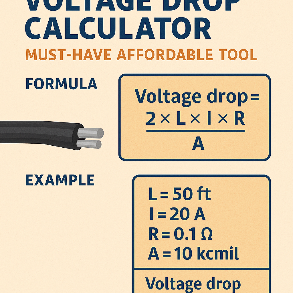
V_drop_DC = I × R_total
- I = load current (A)
- R_total = total conductor resistance (Ω) for the round trip (both conductors)
R_total = R_per_length × L_total
For a two-conductor DC circuit L_total = 2 × L_one_way
AC single-phase circuits (approximate, for installation-level design)
V_drop_1ph = I × (R × L_factor + X × L_factor_reactive)
V_drop_1ph ≈ I × Z_line × L_multiplier
Where:- I = load current (A)
- R = conductor resistance per unit length (Ω/unit length)
- X = conductor reactance per unit length (Ω/unit length)
- Z_line = √(R^2 + X^2) (Ω/unit length)
- L_multiplier = one-way or round-trip multiplier depending on configuration (typically 2 for single-phase with two conductors)
AC three-phase circuits (balanced load)
V_drop_3ph = √3 × I × (R × L_oneway) for line-to-line expressed drop
- I = line current (A)
- R = resistance per unit length per conductor (Ω/unit length)
- L_oneway = one-way conductor length (same units)
- Factor √3 converts phase-to-line relations for balanced three-phase
- For most building wiring short runs (<100 m), conductor reactance X often contributes less than resistance R, but it must be included for long runs, high frequencies, or specific cable constructions.
- Voltage drop calculators typically allow the user to select whether to use pure resistive assumption or full complex impedance.
- NEC guidance and many engineering textbooks recommend designing to keep total voltage drop (supply transformer secondary through branch circuit) under specified percent thresholds (common guidance: 3% on branch, 5% combined).
Key Features a Must-Have Affordable Voltage Drop Calculator Should Provide
An effective tool tailored for engineers and installers should include:- Support for DC, single-phase AC, and three-phase AC calculations with clear selection controls.
- Built-in conductor property database (AWG and metric sizes) including resistance (Ω/1000 ft or Ω/km) and reactance.
- Ability to input custom conductor materials (copper, aluminum) and temperature correction factors.
- Options for one-way vs round-trip length, grouped conductors, multiple parallel conductors, and derating scenarios.
- Integration of code-based limits (user can set percent limits such as 3% or 5%) and automated pass/fail reporting.
- Exportable results (PDF/CSV), traceable calculation details, and configurable unit systems (imperial/metric).
- Clear UX with step-by-step prompts, default typical values, and warnings for unusual inputs.
Extensive Tables: Conductor Resistances and Typical Values
Below are typical resistance values for copper and aluminum conductors. These are representative at 20°C for copper and 20°C for aluminum. Use temperature correction for elevated conductor temperatures per standards.| AWG / mm² | Conductor Type | Cross-Sectional Area (mm²) | Resistance (Ω/1000 ft) | Resistance (Ω/km) | Typical Ampacity (A) | Typical Use |
|---|---|---|---|---|---|---|
| 14 AWG | Copper | 2.08 | 2.525 | 8.28 | 15 | Lighting branch circuits |
| 12 AWG | Copper | 3.31 | 1.588 | 5.20 | 20 | General branch circuits |
| 10 AWG | Copper | 5.26 | 0.999 | 3.27 | 30 | Small appliances |
| 8 AWG | Copper | 8.37 | 0.628 | 2.06 | 55 | Water heaters, ranges (smaller) |
| 6 AWG | Copper | 13.3 | 0.395 | 1.30 | 75 | Service feeders, larger loads |
| 4 AWG | Copper | 21.2 | 0.248 | 0.815 | 95 | Service feeders |
| 2 AWG | Copper | 33.6 | 0.156 | 0.513 | 130 | Large feeders |
| 1/0 AWG | Copper | 53.5 | 0.0983 | 0.323 | 150 | Service conductors |
| 4/0 AWG | Copper | 107.2 | 0.0490 | 0.161 | 230 | Large services, feeders |
| 50 mm² | Aluminum | 50.0 | 0.364 | 1.194 | 150 | Medium feeders |
| 95 mm² | Aluminum | 95.0 | 0.192 | 0.630 | 225 | Large feeders |
- Resistance values are approximate. Manufacturer datasheets and standards (IEC/NEC tables) provide exact entries for specific insulation and temperature ratings.
- A calculator should allow selection between Ω/1000 ft and Ω/km and perform conversions automatically.
| Cable Type | Typical X (Ω/km) | Typical R (Ω/km) at 20°C (Cu) | Use Case |
|---|---|---|---|
| Single-core, insulated, clipped direct (Cu) | 0.08–0.12 | 0.323 (for 1/0 AWG) | Indoor installations, short runs |
| Three-core multi-core SWA (Cu) | 0.07–0.10 | Varies by size | Power distribution, longer lengths |
| Aluminium overhead line conductor | 0.04–0.08 | Higher than Cu per area | Overhead distribution |
Temperature Correction and Skin Effect Considerations
A realistic calculator accounts for temperature dependence of resistance. For copper, resistance increases with temperature approximately linearly near room temperature. Engineers use temperature coefficients:R_T = R_20 × [1 + α × (T - 20°C)]
- R_T = resistance at temperature T
- R_20 = resistance at 20°C
- α ≈ 0.00393 /°C for copper
R_75 = R_20 × [1 + 0.00393 × (75 - 20)] = R_20 × [1 + 0.00393 × 55]
Practical Calculation Workflow (How a Calculator Should Work)
Step-by-step expected workflow:- Input system type: DC / AC single-phase / AC three-phase.
- Specify nominal system voltage and acceptable percent voltage drop limit.
- Enter conductor length (one-way), conductor material, and size selection or allow auto-select.
- Input load: current (A) or power (W/kW) with power factor for AC.
- Select temperature and installation conditions (conduit, buried, aerial) for correction.
- Choose calculation mode: simplified resistive or full impedance (R + jX).
- Run calculation to get Vdrop (V), percent drop (%), and pass/fail status.
- Provide suggested alternative conductor sizes and estimated cost delta for affordability decisions.
Real-World Worked Examples (Detailed Step-by-Step Solutions)
At least two practical cases follow: one residential single-phase branch circuit and one industrial three-phase feeder. Each example includes full calculations, intermediate values, and code-guided decision making.Example 1 — Residential branch circuit: 120 V lighting circuit, 50 m run
Scenario:- System: Single-phase AC, split-phase 120/240 V available; branch is 120 V.
- Load: 12 A continuous lighting load at unity power factor.
- One-way conductor length: 50 m (164.0 ft).
- Conductor: Copper, choose to evaluate 12 AWG and 10 AWG.
- Acceptable voltage drop limit: 3%.
R_per_m_12AWG = 0.00520 Ω/m
L_round = 2 × L_oneway = 2 × 50 m = 100 m
R_total_12AWG = R_per_m_12AWG × L_round = 0.00520 × 100 = 0.52 Ω
V_drop = I × R_total = 12 A × 0.52 Ω = 6.24 V
%drop = (V_drop / 120 V) × 100 = (6.24 / 120) × 100 = 5.2%
- Percent drop = 5.2% which exceeds the 3% target. Not acceptable for recommended lighting circuit limit.
R_total_10AWG = 0.00327 × 100 = 0.327 Ω
V_drop_10AWG = 12 × 0.327 = 3.924 V
%drop_10AWG = (3.924 / 120) × 100 = 3.27%
- Percent drop = 3.27% just above 3% guideline. Practical decision: either accept slightly higher than strict target, shorten run, or use 8 AWG for better margin.
R_per_m_8AWG = 0.00206 Ω/m → R_total = 0.206 Ω → V_drop = 12 × 0.206 = 2.472 V → %drop = 2.06%
- For strict 3% target, select 8 AWG copper. If 3.5% is tolerable, 10 AWG might be accepted with documentation and local authority agreement.
Example 2 — Industrial three-phase feeder: 400 V, 200 A, 120 m run
Scenario:- System: Three-phase, 400 V line-to-line (common in many international installations).
- Load: Balanced three-phase load drawing 200 A per phase, power factor 0.9 (lagging).
- One-way conductor length: 120 m.
- Conductor: Copper, evaluate 95 mm² and 120 mm² alternatives.
- Acceptable voltage drop limit for the feeder: 3% of 400 V = 12 V.
V_drop_3ph = √3 × I × R_per_m × L_oneway
R_95 = 0.000630 Ω/m
V_drop = √3 × 200 A × 0.000630 × 120 m
- √3 ≈ 1.732
- R_total_oneway = 0.000630 × 120 = 0.0756 Ω (per conductor one-way)
- V_drop = 1.732 × 200 × 0.0756 = 1.732 × 15.12 = 26.19 V
%drop = (26.19 / 400) × 100 = 6.55%
R_120 = 0.000500 Ω/m
R_total_oneway = 0.000500 × 120 = 0.06 Ω
V_drop = 1.732 × 200 × 0.06 = 1.732 × 12 = 20.784 V
%drop = (20.784 / 400) × 100 = 5.20%
R_240 = 0.000250 Ω/m → R_total_oneway = 0.03 Ω → V_drop = 1.732 × 200 × 0.03 = 10.392 V → %drop = 2.598%
Conclusion:- To meet a 3% feeder drop (≤12 V), a conductor size approximately 240 mm² copper or parallel conductor arrangement must be used.
- Alternative cost-effective solution: use parallel runs of smaller cables (two runs of 120 mm² in parallel per phase result in half the R and therefore approximately half the drop) or increase system voltage if feasible.
UX and Usability: Making the Tool Affordable but Professional
An affordable tool does not need every enterprise feature; it must deliver core engineering functionality with efficient UI. Recommended UX features:- Pre-filled defaults for typical installations with ability to override.
- Clear unit toggles and conversion helpers.
- Immediate visual pass/fail indicator for percent drop limits.
- Downloadable traceable calculation log for recordkeeping and inspections.
- Guided recommendations: if result fails, propose next conductor sizes and predicted cost delta.
- Implement a reliable conductor database (updateable via CSV).
- Offer both simplified mode (resistive only) and advanced mode (R + jX, harmonics support).
- Validate user inputs (non-negative, plausible ranges) and warn for extreme cases.
- Support local code presets (NEC, IEC) to align output with inspector expectations.
Standards, Normative References, and Authoritative Links
A credible calculator references and aligns with recognized standards and guidance. Key normative documents and sources:- NFPA 70 — National Electrical Code (NEC). See relevant parts on voltage drop guidance and conductor ampacity: https://www.nfpa.org/ (NEC resources)
- IEC standards related to cables and calculation methods, e.g., IEC 60287 for calculation of the continuous current rating of cables: https://www.iec.ch/
- IEEE Standards and guides for power engineering practices, e.g., IEEE Std 141 (Red Book) and IEEE Std 142 (Green Book) provide grounding and distribution guidance: https://standards.ieee.org/
- Manufacturer datasheets and handbooks (Prysmian, Nexans, Southwire) for precise R and X values and installation notes.
- International Electrotechnical Commission (IEC) and CENELEC publications for harmonized practices in Europe: https://www.cenelec.eu/
Implementation Considerations for Software Engineers
If building a voltage drop calculator:- Keep arithmetic in double precision and document rounding behavior.
- Allow for both metric and imperial units and display both when exporting results.
- Make the conductor database updateable and allow import of manufacturer-specific impedance tables.
- Provide API endpoints for integrations with BIM, ERP, and estimating tools to aid procurement decisions.
- Ensure security and data integrity for cloud-based calculators (HTTPS, backups, versioning of conductor tables).
Testing, Validation, and Quality Assurance
Validation steps:- Cross-check calculator outputs against hand calculations for sample scenarios (both DC and AC).
- Compare to manufacturer data and published tables for a range of conductor sizes and lengths.
- Include unit tests for boundary cases: zero length, extremely long lengths, parallel conductors, high temperature correction.
- Perform peer review by licensed electrical engineers and compliance review with local authorities having jurisdiction (AHJ).
Example Output and Reporting (What the Calculator Should Provide)
Output should include:- Summary: input parameters, selected conductor, computed Vdrop (V), percent drop, pass/fail vs target.
- Detailed calculation log: each arithmetic step with the formula used and values substituted.
- Alternative suggestions: next larger conductor sizes, parallel conductor options, and brief cost-impact estimate if unit costs provided.
- Reference citations: which table or standard value was used for conductor resistance and reactance.
Selecting an Affordable Commercial or Open-Source Tool
When evaluating options:- Prefer tools that expose the calculation steps for transparency rather than black-box outputs.
- Check for regular updates to conductor tables and standards mapping.
- Assess export options and integration capabilities for project workflows.
- Consider whether the vendor or community provides QA and peer-reviewed verification.
Maintenance and Recordkeeping Practices
For installations and inspections, maintain:- Saved calculation reports per circuit with date, engineer name, and revision.
- Versions of conductor data and standard references used for the calculation.
- Notes on assumptions (e.g., balanced load, unity power factor, grouping corrections not applied).
Summary of Best Practices (Practical Checklist)
- Always confirm conductor R/X from manufacturer or recognized standards for critical feeders.
- Set conservative percent drop limits for motor loads and sensitive electronics.
- Account for temperature and grouping deratings where applicable.
- Document decisions when accepting higher voltage drop than standard guidance.
- Use the calculator in both simplified and detailed modes to cross-check results.
- NFPA — National Fire Protection Association (NEC): https://www.nfpa.org/
- IEC — International Electrotechnical Commission: https://www.iec.ch/
- IEEE Standards Association: https://standards.ieee.org/
- Prysmian Group technical catalogs (cable resistance and reactance tables): https://www.prysmiangroup.com/
- Southwire technical resources (wire & cable tables): https://www.southwire.com/