This article explains precise methods to calculate short circuit current in power cables and standards
It covers IEC approaches, cable thermal stability, impedance, fault levels, and practical calculator recommendations tools
Short-Circuit Current in Cables — IEC-based Calculator
Scope and importance of short-circuit current calculation for cables
Accurate short-circuit current calculations determine protection settings, cable selection, and system safety. Engineers must reconcile electromagnetic, thermal and protection requirements under international standards. This article focuses on IEC-based methodologies, provides explicit algebraic formulas (expressed in plain HTML text), includes extensive tabulated cable parameters, and develops two complete real-case computations. The objective is to enable engineers to verify prospective fault currents, check adiabatic thermal withstand of conductor cross-sections, and size protection appropriately.Relevant IEC normative framework and authoritative references
Short-circuit calculation methods are standardized and widely referenced in international engineering practice:- IEC 60909 — "Short-circuit currents in three-phase AC systems" (provides rules for calculating uncomplicated and equivalent fault currents and correction factors): https://www.iec.ch
- IEC 60287 — "Electric cables — Calculation of the current rating" (thermal aspects, cable heating): https://www.iec.ch
- IEC 60364 — "Electrical installations of buildings" (protection coordination and selection): https://www.iec.ch
- IEEE Std. 141 (IEEE Green Book) and IEEE Std. 399 (Brown Book) for power system analysis and cable data guidance: https://www.ieee.org
- Manufacturer technical guides (Prysmian, Nexans) for practical impedance and reactance data: https://www.prysmian.com, https://www.nexans.com
Fundamental electrical relationships and algebraic formulas
Use the following basic algebraic relationships for three-phase and single-phase faults. All formulas are provided using plain characters; variables are explained below each formula.Three-phase symmetric fault prospective current
I_sc = U_LL / (sqrt(3) * Z_total)
- I_sc: symmetrical RMS line current during a three-phase fault (A)
- U_LL: nominal line-to-line voltage of the system (V)
- sqrt(3): square root of three (≈ 1.732)
- Z_total: total per-phase impedance seen by the fault (ohm), including source impedance, transformer, lines, cable impedance, and any series impedances
- For faults applied at transformer low-voltage terminals, include transformer internal impedance and source short-circuit contribution.
Per-phase total impedance composition
Z_total = Z_source + Z_transformer + Z_line + Z_cable + Z_load (if relevant)
- Z_source: The Thevenin equivalent impedance of upstream network (ohm)
- Z_transformer: per-phase transformer impedance referred to the chosen voltage side (ohm)
- Z_line / Z_cable: series impedances of overhead lines or cables to the fault point (ohm)
- Z_load: usually negligible for short-circuit calculations except in special configurations
Transformer contribution formula using percent impedance
I_sc_transformer = (S_trated) / (sqrt(3) * U_nom) * (100 / Z_percent)
- I_sc_transformer: prospective short-circuit current assuming transformer only (A)
- S_trated: transformer rated apparent power (VA)
- U_nom: relevant nominal voltage for the side used (V)
- Z_percent: transformer's impedance as percentage of rated base (%)
- S_trated = 500000 VA (500 kVA)
- U_nom = 400 V (LV side)
- Z_percent = 6 (%)
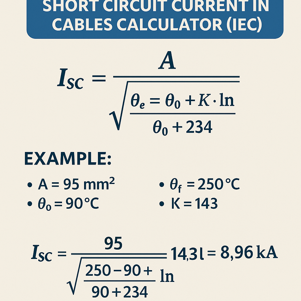
Adiabatic short-circuit thermal withstand equation (IEC-style)
I_adm = k * S / sqrt(t)
- I_adm: admissible symmetrical short-circuit current for duration t (A)
- k: material and temperature-dependent constant (A·s^0.5/mm2)
- S: conductor cross-sectional area (mm2)
- t: prospective fault duration (s)
- This is the classical adiabatic approximation used to verify conductor melting or insulation damage during short circuits (energy balance: Joule heating equals material enthalpy rise).
- k is not universal; values depend on initial temperature, final allowable temperature, and material properties. Always use k values specified in local regulations or calculated from material data per IEC 60909/IEC 60287.
Conversion between complex impedances and magnitudes
|Z| = sqrt(R^2 + X^2)
- |Z|: magnitude of the impedance (ohm)
- R: resistance component at the operating temperature (ohm)
- X: reactance component (ohm)
Typical cable electrical data and reference tabulations
Below are engineering tables of common conductor sizes with approximate DC resistance (R20) at 20 °C and representative reactance X per km for medium-voltage and low-voltage cables. Use these values for preliminary calculations; always consult manufacturer data for project-level designs.| Conductor area (mm2) | R20 (ohm/km) | Typical X (ohm/km) | Common application |
|---|---|---|---|
| 16 | 1.15 | 0.08 | Small LV circuits |
| 25 | 0.727 | 0.075 | LV feeders |
| 35 | 0.524 | 0.073 | LV feeders, motors |
| 50 | 0.387 | 0.07 | LV mains |
| 70 | 0.268 | 0.065 | Large LV feeders |
| 95 | 0.193 | 0.06 | Medium MV/large LV |
| 120 | 0.153 | 0.058 | MV & large feeders |
| 150 | 0.124 | 0.055 | Heavy duty feeders |
| 185 | 0.099 | 0.052 | High capacity feeders, MV |
| 240 | 0.075 | 0.050 | Very large feeders |
- R20 is DC resistance at 20 °C for annealed copper conductors; actual R at operating temperature must be corrected by temperature coefficient.
- Reactance X values are approximate and depend on cable construction, spacing, and system grounding. MV cables often have slightly higher X/km due to conductor configuration and sheath proximity.
| Material / Conditions | Typical k (A·s^0.5/mm2) | Reference condition |
|---|---|---|
| Copper (typical engineering) | 115 – 143 | k depends on initial and final temperatures and assumptions |
| Aluminium | 70 – 95 | Often lower than copper due to higher resistivity and lower heat capacity |
| Lower initial temperature (colder) | higher k | initial conductor cooler increases admissible I |
Accounting for temperature dependence and correction factors
Resistance at operating temperature T (°C) is obtained from:R_T = R_20 * (1 + alpha * (T - 20))
- R_T: resistance at temperature T (ohm)
- R_20: resistance at 20 °C (ohm)
- alpha: temperature coefficient (for copper ≈ 0.00393 /°C)
- T: conductor operating temperature (°C)
- Copper: 0.00393 /°C
- Aluminium: 0.00403 /°C
Practical computational workflow for engineers
Follow this ordered process to produce reliable short-circuit current results:- Define system nominal voltages and the fault location.
- Identify sources and their short-circuit contributions (grid equivalent short-circuit power or internal impedances; transformer %Z).
- Collect cable geometric and electrical data: conductor area, R20, X/km, length, sheath characteristics, and operating temperature.
- Convert resistances to operating temperature and compute per-phase cable impedance Z_cable = L * (R_T/km + j X/km).
- Sum complex impedances to obtain Z_total.
- Compute I_sc symmetrical using I_sc = U_LL / (sqrt(3) * |Z_total|).
- Check adiabatic thermal withstand with I_adm = k * S / sqrt(t). Compare I_sc (or symmetrical RMS) with I_adm for the expected clearing time t.
- Estimate peak values and residual DC offset if required for mechanical stress and protection device selection.
- Document results and reference the normative data used.
Example case 1 — LV distribution: 500 kVA transformer feeding a 50 m cable
Problem statement: A 500 kVA, 400/11 000 V transformer (LV side rated at 400 V) with 6% impedance supplies an LV bus. A 50 m length of 50 mm2 copper XLPE cable (R20 = 0.387 ohm/km, X = 0.07 ohm/km) feeds a distribution board. Determine:- 1) Prospective three-phase fault current at the cable end ignoring other network impedance.
- 2) Whether the cable (S = 50 mm2) can withstand the short-circuit for 0.5 s using adiabatic verification with typical k for copper = 115 (engineering value for demonstration).
I_sc_tr = S_trated / (sqrt(3) * U_nom) * (100 / Z_percent)
- S_trated = 500000 VA
- U_nom = 400 V
- Z_percent = 6
I_sc_tr = 500000 / (1.732 * 400) * (100 / 6) = 500000 / 692.8 * 16.6667
Intermediate: 500000 / 692.8 = 721.7 A (transformer rated current)
I_sc_tr = 721.7 * 16.6667 = 12,028 A ≈ 12.03 kA
- Length L = 50 m = 0.05 km
- R20 per km = 0.387 ohm/km → R_cable = 0.387 * 0.05 = 0.01935 ohm
- X per km = 0.07 ohm/km → X_cable = 0.07 * 0.05 = 0.0035 ohm
- Z_cable = 0.01935 + j 0.0035
- |Z_cable| = sqrt(0.01935^2 + 0.0035^2) = sqrt(0.0003744 + 0.00001225) = sqrt(0.00038665) = 0.01966 ohm
Z_tr = U_LL / (sqrt(3) * I_sc_tr)
Z_tr = 400 / (1.732 * 12028) = 400 / 20848 ≈ 0.01918 ohm
Z_total = Z_tr + Z_cable = (0.01918 + j0) + (0.01935 + j0.0035) = 0.03853 + j0.0035
|Z_total| = sqrt(0.03853^2 + 0.0035^2) = sqrt(0.0014848 + 0.00001225) = sqrt(0.00149705) = 0.0387 ohm
I_sc_end = U_LL / (sqrt(3) * |Z_total|) = 400 / (1.732 * 0.0387) = 400 / 0.0670 = 5970 A ≈ 5.97 kA
Interpretation:- The cable sees a reduced short-circuit current (≈5.97 kA) compared to transformer-only 12.03 kA due to cable impedance.
I_adm = k * S / sqrt(t) = 115 * 50 / sqrt(0.5)
sqrt(0.5) = 0.7071
I_adm = 5750 / 0.7071 = 8133 A ≈ 8.13 kA
- I_sc_end (5.97 kA) < I_adm (8.13 kA) — the conductor cross-section of 50 mm2 is acceptable for a 0.5 s fault duration under these assumptions.
- Use accurate k per IEC tables and exact operating initial conductor temperature; this example is illustrative.
- Consider switchgear interrupting capacity and prospective peak currents for mechanical stresses.
Example case 2 — MV network: 11 kV feeder and utility source
Problem statement: An 11 kV feeder of length 500 m uses 95 mm2 copper conductors with R20 = 0.193 ohm/km and X = 0.06 ohm/km. The upstream utility short-circuit power at the point of supply is S_sc = 100 MVA. Determine the three-phase prospective fault current at the feeder end and check adiabatic withstand of the conductor for a protective device clearing time t = 0.2 s. Assume copper k = 115 for demonstration.Step 1 — Compute cable impedance:- Length L = 0.5 km
- R_cable = 0.193 * 0.5 = 0.0965 ohm
- X_cable = 0.06 * 0.5 = 0.03 ohm
- Z_cable = 0.0965 + j 0.03
- |Z_cable| = sqrt(0.0965^2 + 0.03^2) = sqrt(0.009312 + 0.0009) = sqrt(0.010212) = 0.10105 ohm
Z_source = U_LL^2 / S_sc
- U_LL = 11e3 V
- S_sc = 100e6 VA
Z_source = (11,000^2) / 100,000,000 = 121,000,000 / 100,000,000 = 1.21 ohm
Z_total = Z_source + Z_cable = (1.21 + j0) + (0.0965 + j0.03) = 1.3065 + j0.03
|Z_total| = sqrt(1.3065^2 + 0.03^2) = sqrt(1.707 + 0.0009) = sqrt(1.7079) = 1.3069 ohm
I_sc = U_LL / (sqrt(3) * |Z_total|) = 11,000 / (1.732 * 1.3069)
Denominator = 1.732 * 1.3069 = 2.2639
I_sc = 11,000 / 2.2639 = 4,861 A ≈ 4.86 kA
I_adm = k * S / sqrt(t) = 115 * 95 / sqrt(0.2)
sqrt(0.2) = 0.4472
I_adm = 10925 / 0.4472 = 24,435 A ≈ 24.4 kA
- I_sc (4.86 kA) is much less than I_adm (24.4 kA) for t = 0.2 s — conductor thermal energy capacity is sufficient under these assumptions.
- However, check mechanical electrodynamic forces associated with peak currents and evaluate the cable protection coordination.
Peak current and DC offset considerations
The asymmetrical fault current initial peak (I_peak) can exceed the steady-state symmetrical RMS current due to transient DC offset. The peak depends on fault inception angle and the X/R ratio of the fault loop.A practical approximate estimation can be made with:I_peak ≈ k_p * I_sc
- X/R: ratio of reactance to resistance of the fault loop. Higher X/R yields less DC offset damping and higher potential peak factors.
- Use measured or derived R and X at fault conditions to compute X/R.
Practical notes on calculator design and usage (what a good IEC-based calculator must include)
An effective short-circuit current calculator targeting IEC compliance should:- Allow entry of source short-circuit power (S_sc) or source impedance.
- Support transformer impedance (%Z), rated power, and correct side referencing.
- Accept per-km cable R and X values, length, and operating temperature.
- Compute complex impedance summation with vector arithmetic and present magnitude and phase angle.
- Provide adiabatic checks with selectable k-values and initial temperature options.
- Provide peak and mechanical forces estimations using X/R-based peak factor guidance or IEC 60909 Annex provisions.
- Export detailed calculations and references to normative clauses used.
Verification, uncertainties and good engineering practice
Key sources of uncertainty:- Actual cable impedance differs from catalogue values due to installation conditions, grouping, and mutual coupling.
- Operating temperature affects resistivity; high ambient or grouping increases R and reduces prospective current.
- Utility short-circuit power can vary; obtain up-to-date grid short-circuit values from the network operator.
- Transformer impedance tolerance and measurement uncertainty.
- Request cable manufacturer impedance tables for the specific cable construction and laying arrangement.
- Obtain source short-circuit levels from the utility and use worst-case lower source strength for protective settings.
- Model complex networks with network analysis tools for multi-source and unbalanced faults.
- Document assumptions and provide sensitivity checks (e.g., ±20% source Ssc, different temperature scenarios).
Additional tabulation — common MV cable impedances by construction (example)
| Cable type | Nominal rating | R (ohm/km) | X (ohm/km) | Typical application |
|---|---|---|---|---|
| 3-core XLPE, copper, 11 kV | 95 mm2 | 0.193 | 0.06 | MV distribution feeders |
| 3-core XLPE, copper, 120 mm2 | 120 mm2 | 0.153 | 0.058 | MV feeders |
| Single-core 11 kV, copper, 240 mm2 | 240 mm2 | 0.075 | 0.09 | Long MV circuits |
| Aluminium 3-core 11 kV | 300 mm2 | 0.065 | 0.085 | Economical MV feeders |
References and further reading
- IEC 60909: Short-circuit current calculation standards — official resource: https://www.iec.ch
- IEC 60287: Cables — current rating and thermal calculations: https://www.iec.ch
- IEEE Std 399 (Brown Book): Guide for system modeling and short-circuit calculations: https://standards.ieee.org
- Prysmian Group — technical library and cable impedance data (manufacturer tables): https://www.prysmian.com
- Nexans — cable technical guides and impedance data: https://www.nexans.com
- Cigre and CENELEC publications on MV distribution system short-circuit methodologies
Practical checklist before finalizing design
- Verify source short-circuit power with the network operator.
- Use manufacturer-provided R and X at the operating configuration.
- Apply temperature correction to resistance for expected operating conditions.
- Choose appropriate k values and initial temperatures in adiabatic checks, referencing IEC tables.
- Include safety margins and document worst-case scenarios.
- Check protection device interrupting ratings and settings against prospective currents and peak values.