This tool converts current to real power for AC and DC systems quickly and accurately.
Supports single‑phase, three‑phase, and DC calculations with optional power factor and efficiency adjustments correction limits.
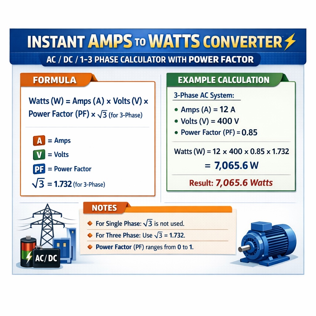
Instant Amps-to-Watts Converter for DC, Single-Phase and Three-Phase Circuits (with Power Factor)
Fundamentals of instant amps-to-watts conversion
The converter calculates active (real) power from measured current using voltage, power factor, and efficiency.
It supports DC, single‑phase AC, and balanced three‑phase AC; results reported in watts (W) and kilowatts (kW).
Key physical quantities and definitions
- Current (I) — electrical current flowing in amperes (A).
- Voltage (V) — potential difference in volts (V); for three‑phase systems specify line‑to‑line (V_LL) or line‑to‑neutral (V_LN).
- Power (P) — active (real) power in watts (W) delivered to useful work; P = W/s.
- Apparent power (S) — product of RMS voltage and RMS current in volt-amperes (VA).
- Power factor (PF) — ratio of real power to apparent power (0 ≤ PF ≤ 1); accounts for phase displacement and waveform distortion.
- Efficiency (η) — equipment conversion efficiency (0 < η ≤ 1), optional when converting input electrical power to output mechanical or usable power.
Conversion formulas for DC, single‑phase AC, and three‑phase AC
DC circuits
For direct current the real power is simply:
Variables:
- V — DC voltage (V)
- I — DC current (A)
- η — efficiency (decimal), default 1.0 if measuring actual electrical power delivered
Typical values: V = 12 V (automotive), 48 V (telecom), 400 V (industrial DC bus); η = 0.98–1.00 for measurement purposes.
Single‑phase AC
For single‑phase alternating current, real power uses the power factor:
Variables:
- V — RMS voltage (V)
- I — RMS current (A)
- PF — power factor (0–1), includes displacement and distortion contributions
- η — optional efficiency term (decimal)
Typical values: V = 120 V, 230 V, 240 V; PF = 0.6–0.99 depending on load type.
Balanced three‑phase AC (line‑to‑line input)
For a balanced three‑phase system using line‑to‑line voltage V_LL:
Alternatively, using line‑to‑neutral voltage V_LN:
Variables:
- V_LL — line‑to‑line RMS voltage (V)
- V_LN — line‑to‑neutral RMS voltage (V) (V_LN = V_LL / √3)
- I_L — line current (A)
- PF — power factor (0–1)
- η — optional efficiency (decimal)
Typical voltages: 400 V (Europe industrial), 480 V (North America industrial), 208 V (US 3‑phase derived from 120/208).
Power factor specifics and measurement considerations
Power factor can be displacement PF (phase angle) or true PF including harmonic distortion. For accurate real power conversion use true PF measured by power analyzers.
- Displacement PF = cos(φ) where φ is fundamental-phase angle between voltage and current.
- Distortion PF accounts for harmonic currents; true PF = P / S, where S = V × I (RMS).
When PF is unknown, conservative engineering practice: assume PF = 0.8 for mixed inductive loads and PF = 1.0 for resistive loads.
Extensive conversion tables for common voltages and currents
The following tables provide instant reference conversions for DC, single‑phase AC, and three‑phase AC at representative voltages and typical PF values. Each table shows P (W) for varying currents.
| DC Voltage (V) | Current (A) | Efficiency η | P = V × I × η (W) | P (kW) |
|---|---|---|---|---|
| 12 | 1 | 1.00 | 12 | 0.012 |
| 12 | 10 | 1.00 | 120 | 0.120 |
| 48 | 5 | 1.00 | 240 | 0.240 |
| 48 | 20 | 0.98 | 940.8 | 0.941 |
| 400 | 1 | 0.99 | 396 | 0.396 |
| 400 | 10 | 0.99 | 3960 | 3.960 |
| 900 | 5 | 1.00 | 4500 | 4.500 |
| Single‑phase V (V) | Current (A) | PF | η | P = V × I × PF × η (W) | P (kW) |
|---|---|---|---|---|---|
| 120 | 1 | 1.00 | 1.00 | 120 | 0.120 |
| 120 | 10 | 0.85 | 0.99 | 1010.4 | 1.010 |
| 230 | 5 | 0.95 | 1.00 | 1092.5 | 1.093 |
| 230 | 20 | 0.80 | 0.98 | 3603.2 | 3.603 |
| 240 | 15 | 0.90 | 0.99 | 3208.8 | 3.209 |
| Three‑phase V_LL (V) | Current I_L (A) | PF | η | P = √3 × V_LL × I_L × PF × η (W) | P (kW) |
|---|---|---|---|---|---|
| 208 | 10 | 0.90 | 1.00 | 3246.6 | 3.247 |
| 400 | 5 | 0.85 | 0.99 | 2912.8 | 2.913 |
| 480 | 20 | 0.95 | 0.98 | 15751.8 | 15.752 |
| 415 | 50 | 0.80 | 0.97 | 13985.7 | 13.986 |
| 600 | 100 | 0.90 | 0.99 | 92376.0 | 92.376 |
Step-by-step calculation procedures for the instant calculator
- Select converter mode: DC, single‑phase AC, or three‑phase AC.
- Enter measured RMS current (I) and the nominal voltage (V) appropriate to mode.
- Enter power factor (PF) for AC modes; if unknown, choose conservative default (e.g., 0.8).
- Enter equipment efficiency (η) if converting from electrical input to useful output power.
- Compute apparent power S and then real power P using the formulas provided.
- Report results in W and kW; include apparent power and reactive power if requested: Q = √(S^2 − P^2).
Reactive power and apparent power calculations
When PF is known, apparent power S and reactive power Q are:
These relationships are essential if the converter provides VA and var outputs for power quality and sizing of infrastructure.
Real-world example 1 — DC system: telecom battery feed
Scenario: A telecom cabinet draws 48 V DC at measured 12.5 A. Determine delivered power and account for a 98% inverter efficiency.
Step 1: Identify variables:
- V = 48 V
- I = 12.5 A
- η = 0.98 (inverter or distribution efficiency)
- PF not applicable for DC
Step 2: Apply DC formula:
Step 3: Present results:
- Electrical input power before losses: 48 × 12.5 = 600 W
- Delivered usable power after 98% efficiency: 588 W = 0.588 kW
- If quoted without efficiency, report both gross and net values for equipment sizing.
Real-world example 2 — Single‑phase AC: commercial lighting circuit
Scenario: A lighting circuit at 230 V supplies an RMS current of 16 A with PF measured at 0.88. Determine real power and apparent power.
Step 1: Identify variables:
- V = 230 V
- I = 16 A
- PF = 0.88
- η = 1.00 (assuming direct electrical consumption)
Step 2: Apply single‑phase formula:
Step 3: Apparent power and reactive power:
Q ≈ √3,052,887 ≈ 1747.25 var
Step 4: Present results:
- Real power P = 3,238.4 W (3.24 kW)
- Apparent power S = 3,680 VA
- Reactive power Q ≈ 1,747.3 var
- Power factor check: PF = P / S = 3,238.4 / 3,680 ≈ 0.88 (consistent)
Real-world example 3 — Balanced three‑phase AC: industrial motor load
Scenario: A three‑phase induction motor operates on a 400 V line‑to‑line supply, with measured line current 75 A and PF = 0.86, motor controller efficiency 0.95. Compute input electrical power.
Step 1: Variables:
- V_LL = 400 V
- I_L = 75 A
- PF = 0.86
- η = 0.95
Step 2: Apply three‑phase formula:
Numeric computation: √3 ≈ 1.73205
Then 1.73205 × 30,000 ≈ 51,961.5
Multiply by PF: 51,961.5 × 0.86 ≈ 44,697.69
Step 3: Apparent power S and reactive Q:
Step 4: Present results:
- Electrical input (gross) before controller losses: ≈ 44.698 kW
- Electrical power delivered after controller efficiency: ≈ 42.463 kW
- Apparent power: ≈ 51.962 kVA
- Reactive power: ≈ 24.083 kVAr
Practical considerations for accurate conversions
- Use true RMS meters for non‑sinusoidal waveforms; harmonic content can significantly affect PF and S.
- Distinguish between displacement PF and true PF; for loads with drives, furnaces, or rectifiers, measure true PF.
- For unbalanced three‑phase loads the balanced formulas only approximate total power. For high accuracy, measure all three line currents and phase-to-neutral voltages and compute per‑phase power.
- Include temperature, conductor losses, and harmonic derating for equipment sizing when converting continuous loads.
Algorithmic flow for an instant online calculator
- Input type selection: DC / single‑phase AC / three‑phase AC.
- Request inputs: I (A), V (V), PF (AC only), η (optional), system configuration (V_LL or V_LN for three‑phase).
- Validation: ensure PF in (0,1], positive numeric values for V and I.
- Calculate S, P, Q as required using formulas above and display results with appropriate unit conversions.
- Provide optional detail: per‑phase results, apparent/reactive power, and energy estimation (kWh) using operating hours.
Energy estimation and thermal considerations
When converting amps to watts for energy forecasting, multiply instantaneous power by time to obtain energy:
Use thermal considerations to derive required conductor ampacity and heat dissipation:
- Conductor losses: I^2 × R cause heating; size conductors to limit temperature rise.
- Enclosure heating: convert wasted power (1 − η) × P_input into thermal load for ventilation sizing.
Verification and compliance with standards
For regulatory and engineering compliance use standardized voltage levels, measurement methods, and reporting formats as defined by international standards.
- IEC 60038 — Standard voltages (reference nominal AC and DC voltages).
- IEC 61000 series — EMC and measurement of power quality parameters including harmonics.
- IEEE Std 1459 — Definitions for power components in electrical systems under nonsinusoidal conditions.
- NIST — Measurement science references for electrical quantities and calibration.
Standards and authoritative references
Relevant normative and technical references for converters, measurement accuracy, and power calculations include:
- IEC 60038: Standard voltages — International Electrotechnical Commission: https://www.iec.ch
- IEEE Std 1459 — IEEE definitions for power components: https://standards.ieee.org
- IEC 61000‑4‑30 — Power quality measurement methods: https://www.iec.ch
- NIST calibration and measurement services: https://www.nist.gov
- U.S. Department of Energy — energy conversion and efficiency guidance: https://www.energy.gov
Best practices for implementing an instant converter with power factor option
- Default to PF = 1.0 for purely resistive DC loads; provide user option to enter measured PF for AC.
- Expose both gross electrical input power and net usable power after efficiency to support sizing and billing analysis.
- Provide apparent power (VA) and reactive power outputs for infrastructure planning (transformer and capacitor bank sizing).
- Offer advanced mode to accept harmonic distortion or per‑phase inputs for unbalanced systems and non‑sinusoidal currents.
- Validate inputs and warn when PF or η values are outside typical engineering bounds.
SEO and operational metadata guidance for deployment
- Ensure page meta description succinctly contains keywords: "Instant Amps to Watts Converter, AC DC, 1/3 Phase Calculator, Power Factor Option".
- Include accessible markup for each result with ARIA labels and tabular data for screen readers.
- Provide machine‑readable download of calculation report (CSV) for audit and verification by engineers.
Appendix — quick reference formulas and variable table
Compact formula suite:
- DC: P = V × I × η
- Single‑phase AC: P = V × I × PF × η
- Three‑phase AC (line‑to‑line): P = √3 × V_LL × I_L × PF × η
- Apparent power (S): single‑phase S = V × I; three‑phase S = √3 × V_LL × I_L
- Reactive power (Q): Q = √(S^2 − P^2)
| Symbol | Meaning | Units | Typical engineering range |
|---|---|---|---|
| V | Voltage (RMS for AC, nominal for DC) | V | 12–600 V (common) |
| I | Current (RMS) | A | 0.01–1000 A depending on system |
| P | Real (active) power | W / kW | 0–MW |
| S | Apparent power | VA / kVA | 0–MVA |
| Q | Reactive power | var / kVAr | 0–Mvar |
| PF | Power factor | unitless | 0.6–1.0 typical |
| η | Efficiency (decimal) | unitless | 0.5–0.995 depending on equipment |
| V_LL | Line‑to‑line voltage (three‑phase) | V | 208, 400, 480, 600 V common |
Final engineering notes
- Document measurement uncertainty and instrument class when reporting converted power for compliance or billing.
- For instrumentation deployed in the field, log harmonic spectra and PF trends to detect power quality degradation early.
- When designing an interface, allow users to choose whether they supply net (post‑efficiency) or gross power expectations.
Further reading and external resources
- IEC — International Electrotechnical Commission (standards and normative references): https://www.iec.ch
- IEEE Standards Association (power definitions and measurement guidance): https://standards.ieee.org
- NIST — calibration services and electrical measurement guidance: https://www.nist.gov
- U.S. Department of Energy — resources on energy efficiency and power systems: https://www.energy.gov