This technical guide explains converting voltage, current, and power factor into kilowatts and kVA accurately.
It addresses balanced and unbalanced systems, providing formulas, examples, and normative references for verification purposes.
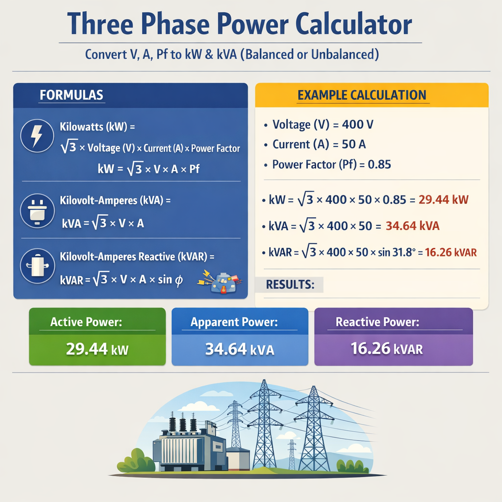
Three-Phase Power Converter: V, A, PF → kW / kVA (Balanced or Unbalanced)
Scope and practical objectives
This article provides precise methods to calculate three-phase real power (kW) and apparent power (kVA) from measured voltage (V), current (A), and power factor (PF). It covers both balanced and unbalanced systems, instrument selection, phasor relationships, and normative references for verification and design.
Fundamental principles for three-phase power conversion
Three-phase power systems transfer energy using three sinusoidal voltages spaced 120 degrees apart. Knowing line-to-line voltage, line current, and power factor allows conversion to real power and apparent power using standard formulae. For unbalanced systems, per-phase calculations must be summed vectorially if phase angles differ significantly.
Basic formulae for balanced three-phase systems
Use the following expressions for a balanced three-phase system.
- Real power (kW): P = √3 × V_L × I_L × PF / 1000
- Apparent power (kVA): S = √3 × V_L × I_L / 1000
- Reactive power (kVAr): Q = √(S^2 − P^2) or Q = √3 × V_L × I_L × sin(phi) / 1000
Variable definitions and typical values
- V_L (line-to-line voltage in volts, V). Typical values: 400 V (Europe), 415 V (industrial), 480 V (North America industrial), 690 V (heavy industry).
- I_L (line current in amperes, A). Typical values depend on power and application; examples: 10 A, 32 A, 63 A, 125 A, 400 A.
- PF (power factor, unitless). Typical values: 0.6 (highly inductive), 0.8 (common industrial loads corrected), 0.95 (motor with correction), 1.0 (purely resistive).
- S (apparent power in kVA). Use to size transformers, protective equipment, and cabling margins.
- P (real power in kW). Use for energy billing, engine sizing, and thermal design.
- Q (reactive power in kVAr). Use for power factor correction and reactive compensation planning.
Why differentiate kW and kVA?
kW represents the real power consumed by loads to perform work. kVA is the total apparent power demanded from the supply irrespective of phase displacement. Equipment such as transformers and switchgear are often rated in kVA because their heating and saturation depend on apparent current and voltage, not only the real component.
Relationship between P, S and PF
- P (kW) = S (kVA) × PF
- S (kVA) = P (kW) / PF
- PF = cos(phi), where phi is the phase angle between voltage and current
Detailed formula set (HTML-only expressions)
Below are the essential formulae shown using plain characters and symbols.
- For balanced three-phase: P (kW) = √3 × V_L (V) × I_L (A) × PF / 1000
- For balanced three-phase: S (kVA) = √3 × V_L (V) × I_L (A) / 1000
- Per-phase (star-connected): P_phase = V_phase × I_phase × PF (W); V_phase = V_L / √3
- Unbalanced total real power: P_total = P_A + P_B + P_C (sum of per-phase real powers)
- Per-phase apparent: S_phase = V_phase × I_phase (VA)
- Unbalanced apparent power (vector sum): S_total = sqrt((ΣP_phase)^2 + (ΣQ_phase)^2) / 1000
Explanation of per-phase unbalanced approach
For unbalanced loads, treat each phase independently: measure or compute phase voltage, phase current, and phase angle. Compute P_phase = V_phase × I_phase × cos(phi_phase). Sum P_phase values to obtain total real power. For apparent power, compute each phase S_phase = V_phase × I_phase and then perform vector summation combining phase angles, or sum squared real and reactive components to obtain total S_total.
Measurement and instrumentation guidance
Accurate conversion requires correct instrumentation and measurement methods. Use true RMS meters and power analyzers with phase-angle measurement capability for non-sinusoidal or distorted waveforms. Clamp meters are acceptable for approximations when harmonics are negligible.
Recommended instruments and settings
- Three-phase power analyzer capable of measuring V_L, I_L, PF, P, Q, and S directly.
- True RMS clamp-on meters for current measurement where direct connection is impractical.
- Voltage transformers (VT/PT) and current transformers (CT) where voltages or currents exceed instrument ranges; use correct CT/VT ratios.
- Record and use per-phase angle (phi) when loads are significantly reactive or when harmonics are present.
Common system voltages and currents — reference tables
The following tables provide common combinations of line voltages, typical currents, PF values, and the resulting kW and kVA for balanced operation. Use them as quick references for sizing and estimation. Each table lists realistic load points for industrial and commercial systems.
| Line Voltage (V) | Line Current (A) | Power Factor | Apparent Power S (kVA) | Real Power P (kW) |
|---|---|---|---|---|
| 400 | 10 | 0.8 | √3×400×10/1000 = 6.928 kVA | 6.928×0.8 = 5.542 kW |
| 400 | 32 | 0.85 | 22.169 kVA | 18.844 kW |
| 415 | 63 | 0.9 | √3×415×63/1000 = 45.346 kVA | 40.811 kW |
| 480 | 125 | 0.95 | √3×480×125/1000 = 103.923 kVA | 98.727 kW |
| 690 | 400 | 0.92 | √3×690×400/1000 = 477.143 kVA | 438.172 kW |
| Application | Typical V_L (V) | Typical I_L (A) | PF Range | Use Case / Notes |
|---|---|---|---|---|
| Small motor | 400 | 10–32 | 0.75–0.9 | Motor starting currents cause transient unbalance; use locked-rotor considerations. |
| Distribution board | 415 | 32–125 | 0.8–0.95 | Loads often mixed; monitor for harmonic distortion. |
| Large motor or plant | 480–690 | 125–1000+ | 0.85–0.95 | Transformers sized by kVA; factor correction recommended. |
| UPS input | 400–480 | 10–400 | 0.95–1.0 | High PF due to inverter control; measure true power. |
Balanced three-phase worked example (Case 1)
The following worked example demonstrates step-by-step calculation for a balanced three-phase load.
Problem statement
A balanced three-phase motor is operating on a 415 V supply. The line current measured is 63 A and the measured power factor is 0.90. Calculate:
- Apparent power S (kVA)
- Real power P (kW)
- Reactive power Q (kVAr)
Solution (step-by-step)
- Apparent power (balanced): S = √3 × V_L × I_L / 1000
- Compute √3 ≈ 1.732
- Plug values: S = 1.732 × 415 × 63 / 1000
- Calculate numerator: 1.732 × 415 = 718. 718 × 63 = 45234 (approx)
- S ≈ 45.234 kVA (rounded to three decimals: 45.234 kVA)
- Real power: P = S × PF = 45.234 × 0.90 = 40.711 kW
- Reactive power: Q = √(S^2 − P^2) = √(45.234^2 − 40.711^2)
- Compute squares: 45.234^2 ≈ 2046.2; 40.711^2 ≈ 1657.2
- Q = √(2046.2 − 1657.2) = √(389.0) ≈ 19.723 kVAr
Results
- S ≈ 45.23 kVA
- P ≈ 40.71 kW
- Q ≈ 19.72 kVAr
Unbalanced three-phase worked example (Case 2)
Unbalanced systems require per-phase evaluation. This example demonstrates handling different currents in each phase with given phase angles.
Problem statement
Three-phase, 400 V line-to-line supply feeding an unbalanced load. Measured per-phase line currents and power factors:
- Phase A: I_A = 50 A, PF_A = 0.95 (lagging)
- Phase B: I_B = 40 A, PF_B = 0.80 (lagging)
- Phase C: I_C = 60 A, PF_C = 0.70 (lagging)
Assume line-to-line voltage V_L = 400 V (balanced voltage). Compute total P (kW), total S (kVA) approximated by scalar summation of per-phase apparent powers, and total Q (kVAr).
Solution (step-by-step)
- Compute per-phase apparent power using S_phase = √3 × V_L × I_phase / 1000? For per-phase apparent in three-phase context, use S_phase = V_phase × I_phase where V_phase = V_L / √3. Equivalent result is S_phase = (√3 × V_L × I_phase / 1000) / 3 ×? To avoid confusion, compute per-phase using line-to-line conversion: S_phase (kVA per phase) = V_phase × I_phase / 1000, where V_phase = V_L / √3.
- Compute V_phase = 400 / 1.732 ≈ 231.0 V
- Per-phase apparent powers (VA): S_A = 231.0 × 50 = 11550 VA = 11.55 kVA
- S_B = 231.0 × 40 = 9240 VA = 9.24 kVA
- S_C = 231.0 × 60 = 13860 VA = 13.86 kVA
- Per-phase real powers: P_phase = V_phase × I_phase × PF
- P_A = 231.0 × 50 × 0.95 = 10972.5 W = 10.973 kW
- P_B = 231.0 × 40 × 0.80 = 7392 W = 7.392 kW
- P_C = 231.0 × 60 × 0.70 = 9693 W = 9.693 kW
- Total real power P_total = P_A + P_B + P_C = 10.973 + 7.392 + 9.693 = 28.058 kW
- Per-phase reactive powers Q_phase = √(S_phase^2 − P_phase^2)
- Q_A = √(11.55^2 − 10.973^2) = √(133.403 − 120.406) ≈ √(12.997) = 3.606 kVAr
- Q_B = √(9.24^2 − 7.392^2) = √(85.378 − 54.636) ≈ √(30.742) = 5.543 kVAr
- Q_C = √(13.86^2 − 9.693^2) = √(192.099 − 93.962) ≈ √(98.137) = 9.906 kVAr
- Total reactive Q_total = Q_A + Q_B + Q_C = 3.606 + 5.543 + 9.906 = 19.055 kVAr
- Scalar apparent S_scalar_sum = S_A + S_B + S_C = 11.55 + 9.24 + 13.86 = 34.65 kVA (approximate by scalar sum)
- Vectorial total apparent S_vector = √(P_total^2 + Q_total^2) = √(28.058^2 + 19.055^2) = √(787.25 + 363.10) = √1150.35 = 33.92 kVA
Results
- P_total ≈ 28.06 kW
- Q_total ≈ 19.06 kVAr
- S_vector ≈ 33.92 kVA (best for equipment sizing)
- S_scalar_sum ≈ 34.65 kVA (approximation if phase angles ignored)
Implementation notes and calculator algorithm
When implementing a three-phase power calculator (software or spreadsheet), follow this algorithmic flow to ensure correct handling of balanced and unbalanced scenarios.
- Input acquisition:
- Accept line-to-line voltage V_L (or per-phase V_phase), measured currents for each phase I_A, I_B, I_C, and power factors or phase angles per phase.
- Accept a flag indicating balanced vs. unbalanced. If balanced, a single current and PF may be provided.
- Normalize inputs:
- If PF given as lagging/leading, interpret sign for reactive computations.
- Compute V_phase = V_L / √3 when needed.
- Balanced computation branch:
- Compute S = √3 × V_L × I_L / 1000.
- Compute P = S × PF.
- Compute Q = √(S^2 − P^2).
- Unbalanced computation branch:
- For each phase compute P_phase = V_phase × I_phase × PF_phase.
- Compute Q_phase = V_phase × I_phase × sin(phi_phase) or Q_phase = √(S_phase^2 − P_phase^2).
- Sum P_total = ΣP_phase; Q_total = ΣQ_phase.
- Compute S_total = √(P_total^2 + Q_total^2).
- Output formatting:
- Provide P_total in kW, Q_total in kVAr, S_total in kVA, and individual phase values.
- Include power factor overall = P_total / S_total.
Standards, normative references and authoritative links
Designers and engineers should cross-check calculations against authoritative standards and local regulations. Below are key normative documents and resources:
- IEC 60909 — Short-circuit current calculation in three-phase systems (useful for equipment sizing): https://www.iec.ch
- IEC 60076 — Power transformers standard for ratings, temperature rise, and kVA sizing: https://www.iec.ch
- IEEE Std 141 (Red Book) — Grounding and power system analysis guidance: https://standards.ieee.org
- IEEE Std 1410 — Harmonics and power quality guidance and measurement techniques: https://standards.ieee.org
- NFPA 70 (NEC) — Electrical safety requirements and equipment ratings in North America: https://www.nfpa.org
- BS EN 50160 — Voltage characteristics of electricity supplied by public distribution networks: https://standards.bsigroup.com
Practical considerations for accuracy
Real-world measurements require attention to instrumentation, harmonics, and transient behavior. Below are common error sources and mitigation techniques:
- Harmonics: Distorted waveforms affect PF and true RMS readings. Use instruments capable of harmonic analysis and true power measurement.
- CT/VT ratios: Ensure correct scaling when using transformers. Verify phase polarity to avoid sign errors.
- Sampling rate: For transient loads and switching devices, ensure sampling frequency is sufficient to capture dynamics.
- Temperature and conductor impedance: For long feeders, voltage drop affects V_phase and current distribution; account for voltage drop when calculating per-phase powers.
- Phase sequence and vector summation: When summing apparent powers vectorially, include phase angles to avoid over- or underestimation.
Sizing equipment from calculated values
When sizing transformers, switchgear, or cables, use S_total (kVA) with an appropriate safety factor. Consider inrush currents, continuous loading limits, and ambient temperature ratings defined in standards such as IEC 60076 and local codes.
Troubleshooting discrepancies between measured and computed power
When computed power does not match expected meter readings, follow systematic checks:
- Verify measurement instrument calibration and CT/VT ratios.
- Check for harmonics or non-sinusoidal loads; measure total harmonic distortion (THD).
- Confirm phase angles and power factor sign (lagging vs. leading).
- Validate wiring and phase sequence to ensure measured currents correspond to correct voltages.
- For unbalanced systems, inspect load distribution and neutral current contributions.
Additional worked example (Case 3): Generator sizing from known loads
This case computes the generator kVA requirement for a plant with mixed balanced and unbalanced loads.
Problem statement
Plant loads:
- Three identical motors: each motor draws 75 kW at PF 0.9, balanced on three phases.
- Lighting loads: 30 kW, PF 0.98, balanced.
- Miscellaneous single-phase unbalanced loads causing neutral current equivalent of 5 kW at PF 0.95.
- Total motor real power P_motors = 3 × 75 = 225 kW
- Motor apparent per motor S_motor = P_motor / PF = 75 / 0.9 = 83.333 kVA; total motors S_total_motors = 3 × 83.333 = 250.0 kVA
- Lighting apparent S_lighting = 30 / 0.98 = 30.612 kVA
- Miscellaneous apparent S_misc = 5 / 0.95 = 5.263 kVA (single-phase unbalanced component)
- Approximate aggregated apparent S_approx = S_total_motors + S_lighting + S_misc = 250 + 30.612 + 5.263 = 285.875 kVA
- Add safety margin 25%: Required generator kVA = 285.875 × 1.25 = 357.344 kVA
- Round up to next standard generator size: 400 kVA is appropriate considering additional transient and future growth.
- Because motors have high starting currents, static kVA summation underestimates transient demands; coordination with motor starting method (soft starter, VFD) can reduce peak kVA requirement.
- Power factor correction can lower required kVA and reduce generator fuel consumption.
- three phase power calculator
- convert V A PF to kW kVA
- balanced unbalanced three phase
- kW kVA conversion formula
- power factor correction and sizing
- per-phase power calculation
- Use true RMS meters and power analyzers for non-sinusoidal loads.
- Record per-phase voltages and currents; do not assume perfect balance unless verified.
- Apply CT and VT scaling factors carefully; verify polarity and phase alignment.
- When sizing equipment, use vector S_total = √(P_total^2 + Q_total^2) and include appropriate safety margins.
- Consider power factor correction to reduce kVA demand and improve efficiency.
- Document calculations and measurement uncertainty for auditability and verification.
- IEC standards portal — https://www.iec.ch (search IEC 60076, IEC 60909)
- IEEE Standards Association — https://standards.ieee.org (search IEEE 141, IEEE 519 for harmonics)
- NEMA resources — https://www.nema.org (transformer and motor standards)
- NFPA (NEC) — https://www.nfpa.org (electrical safety and equipment rating guidance)
- British Standards Institution — https://www.bsigroup.com (BS/EN 50160 and related)
Supply voltage: 480 V line-to-line. Determine minimum generator kVA rating with a safety margin of 25% for starting currents and transient loads.
Solution (step-by-step)
Notes
SEO and engineering keywords to include in implementations
Best practices checklist for field engineers
References and further reading
Final operational guidance
Accurate conversion from V, A, and PF to kW and kVA enables correct equipment sizing, energy billing calculations, and power quality mitigation. Always corroborate computed values with measurement tools and normative guidance for safe, reliable engineering decisions.