Calculator methods for transformer kVA to full-load amps are essential for electrical system design engineering.
This article details single-phase and three-phase calculations, rules, examples, code references, and practical tips practices.
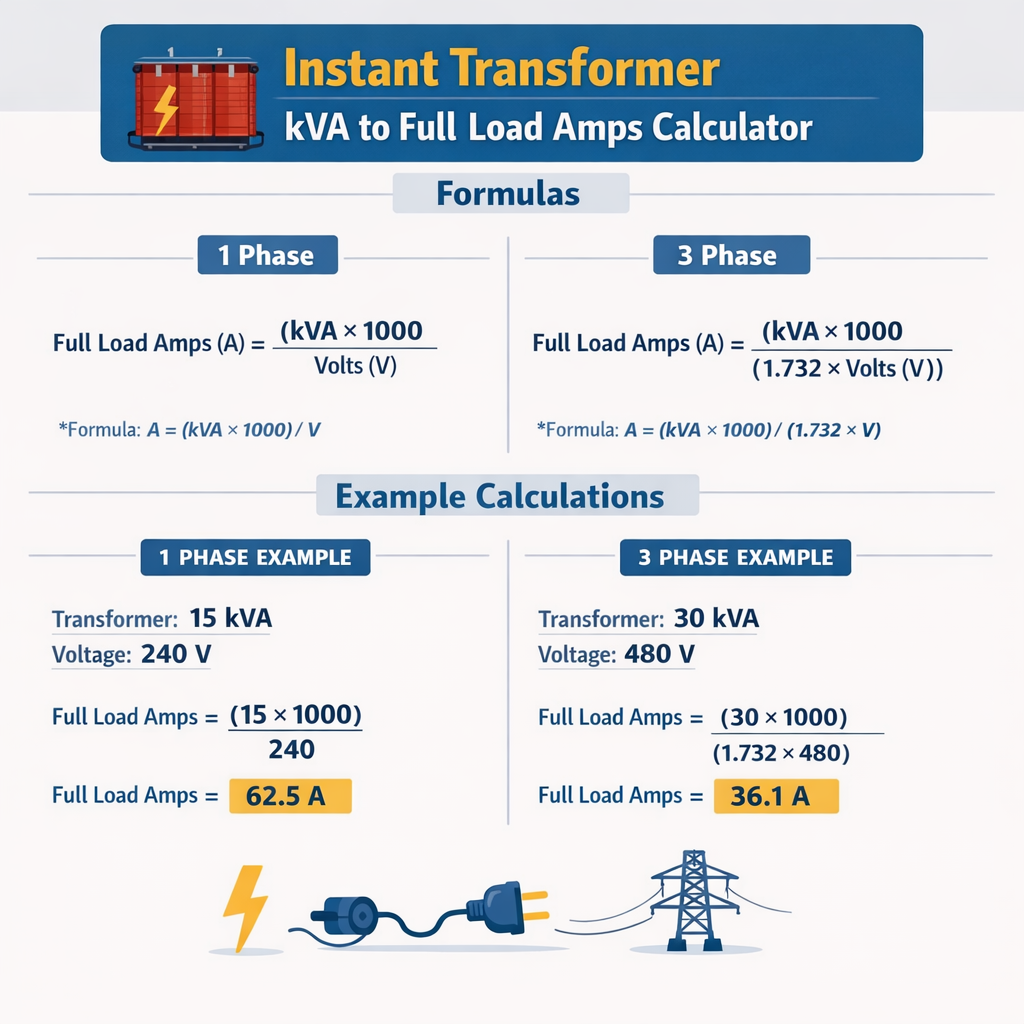
Instant Transformer kVA to Full-Load Amps Calculator (Single-Phase and Three-Phase)
Fundamental formulas and core definitions
Transformer sizing and full-load current conversion use basic power relationships expressed in apparent power (kVA), voltage, and phase.
Single-phase full-load current
Where:
- I = full-load current in amperes (A)
- kVA = transformer rated apparent power in kilovolt-amperes
- V = line-to-line voltage for single-phase circuits in volts (V)
Typical numeric values: kVA = 1, V = 120 → I = (1 × 1000) / 120 = 8.33 A.
Three-phase full-load current
Where:
- I = full-load current in amperes (A)
- kVA = transformer rated apparent power in kilovolt-amperes
- V = line-to-line voltage for the three-phase system in volts (V)
- √3 ≈ 1.732 (factor for balanced three-phase systems)
Typical numeric values: kVA = 100, V = 480 → I = (100 × 1000) / (1.732 × 480) ≈ 120.3 A.
Additional essential factors in practical calculations
Power factor and real power considerations
The kVA rating is apparent power. Real power (kW) is kVA × power factor (PF). If you know kW and PF, convert:
Variables:
- kW = real power in kilowatts
- PF = power factor (typical industrial motors 0.8 lagging, resistive loads 0.95–1.0)
Efficiency and load profile
- Transformer efficiency (η) affects losses but not the nominal kVA-to-current conversion; use η to estimate input kVA for a required output kW: kVA_in = (kW / PF) / η.
- Consider load diversity and duty cycle. Continuous loads (per code) require 125% sizing of conductors and overcurrent protection considerations.
Inrush current and short-time ratings
- Transformer magnetizing inrush can be 6–15× rated current for a cycle or two. Account for selective coordination and device withstand.
- Use inrush-limiting measures when coordination or nuisance tripping is a concern (pre-inrush resistors, NTCs, inrush limiters, controlled switching).
Practical conversion tables for common voltages and kVA ratings
Reference tables below show full-load currents for common single-phase and three-phase voltages and standard kVA sizes. Values rounded to two decimals.
| kVA | Single-phase 120 V (A) | Single-phase 240 V (A) |
|---|---|---|
| 0.25 | 2.08 | 1.04 |
| 0.5 | 4.17 | 2.08 |
| 1 | 8.33 | 4.17 |
| 2 | 16.67 | 8.33 |
| 5 | 41.67 | 20.83 |
| 7.5 | 62.50 | 31.25 |
| 10 | 83.33 | 41.67 |
| 15 | 125.00 | 62.50 |
| 25 | 208.33 | 104.17 |
| 37.5 | 312.50 | 156.25 |
| 50 | 416.67 | 208.33 |
| 75 | 625.00 | 312.50 |
| 100 | 833.33 | 416.67 |
| 150 | 1250.00 | 625.00 |
| 225 | 1875.00 | 937.50 |
| 300 | 2500.00 | 1250.00 |
| 500 | 4166.67 | 2083.33 |
| 750 | 6250.00 | 3125.00 |
| 1000 | 8333.33 | 4166.67 |
| kVA | 3φ 208 V (A) | 3φ 400 V (A) | 3φ 415 V (A) | 3φ 480 V (A) | 3φ 600 V (A) |
|---|---|---|---|---|---|
| 0.25 | 0.69 | 0.36 | 0.35 | 0.30 | 0.24 |
| 0.5 | 1.39 | 0.72 | 0.70 | 0.60 | 0.48 |
| 1 | 2.78 | 1.44 | 1.39 | 1.20 | 0.96 |
| 2 | 5.55 | 2.89 | 2.78 | 2.41 | 1.92 |
| 5 | 13.88 | 7.21 | 6.96 | 6.02 | 4.81 |
| 7.5 | 20.83 | 10.82 | 10.43 | 9.02 | 7.22 |
| 10 | 27.76 | 14.43 | 13.91 | 12.03 | 9.62 |
| 15 | 41.64 | 21.64 | 20.86 | 18.05 | 14.44 |
| 25 | 69.40 | 36.07 | 34.78 | 30.07 | 24.06 |
| 37.5 | 104.10 | 54.10 | 52.17 | 45.11 | 36.09 |
| 50 | 138.80 | 72.14 | 69.57 | 60.15 | 48.11 |
| 75 | 208.20 | 108.21 | 104.66 | 90.23 | 72.17 |
| 100 | 277.60 | 144.29 | 139.14 | 120.30 | 96.23 |
| 150 | 416.40 | 216.44 | 208.71 | 180.45 | 144.34 |
| 225 | 624.60 | 324.66 | 313.07 | 270.68 | 216.51 |
| 300 | 833.00 | 432.86 | 417.28 | 361.36 | 288.68 |
| 500 | 1388.00 | 721.43 | 695.71 | 601.50 | 481.13 |
| 750 | 2082.00 | 1082.15 | 1043.57 | 902.25 | 721.70 |
| 1000 | 2776.00 | 1442.86 | 1391.43 | 1203.00 | 962.26 |
Design considerations, safety factors, and code rules
Continuous loads
Per typical electrical codes, including NFPA 70 (NEC), continuous loads (loads expected to run for three hours or more) must be considered when sizing conductors and overcurrent protection. A common design practice:
Where I_full_load is calculated from kVA to amps. For example, if transformer full-load current is 100 A and the load is continuous, size conductors for 125 A.
Overcurrent protection for transformers
- NEC Article 450 governs overcurrent protection for transformers. Use manufacturer recommendations and NEC allowable limits for primary and secondary protective devices.
- Primary and secondary device sizing depends on transformer type (delta/wye), location, and whether the transformer supplies continuous loads.
Service, neutral, and grounding implications
- Single-phase loads may impose neutral currents; evaluate conductor ampacity and neutral sizing, especially for unbalanced three-phase systems.
- Grounding and bonding must follow NEC Article 250 and local utility rules; transformer grounding methods (delta, grounded-wye, corner-grounded) affect fault currents and protection coordination.
Step-by-step calculation workflow for engineers
- Identify load type: continuous, non-continuous, motor starting requirements, inrush.
- Estimate real power (kW) and power factor (PF) or use specified kVA.
- Compute required kVA: if starting from kW, kVA = kW / PF. Add margin for growth if required (typical 10–25%).
- Select system voltage and phase configuration (single-phase or three-phase).
- Compute full-load current using the relevant formula.
- Apply code multipliers (125% for continuous loads) to define conductor ampacity and protection.
- Select equipment (transformer standard kVA size, breakers, fuses) rounding up to standard sizes and considering inrush/coordination.
- Document assumptions, tolerances, and reference standards.
Two detailed worked examples
Example 1 — Single-phase distribution for a commercial lighting bank
Scenario: A small retail tenant requires 20 kW of lighting load on a single-phase 240 V feeder. Lighting is expected to operate continuously (store hours exceed three hours). Power factor is high (assume PF = 0.98). Determine required transformer kVA, full-load amps, conductor ampacity for continuous load, and recommended breaker size.
Step 1 — Convert kW to kVA:
kVA_required = kW / PF = 20 / 0.98 = 20.408 kVA → use 20.5 kVA nominal (or select 25 kVA standard transformer).
Step 2 — Compute full-load current on single-phase 240 V:
I_full = (kVA × 1000) / V = (20.408 × 1000) / 240 = 85.03 A.
Step 3 — Apply continuous load factor (1.25) per code for conductor sizing:
Required conductor ampacity = 85.03 × 1.25 = 106.29 A.
Step 4 — Select conductor and overcurrent protection:
- Round conductor ampacity up to a common conductor size with ampacity ≥ 106.29 A (e.g., 3/0 Cu THHN has ampacity ~200 A in many installations; 3/0 may be conservative; 1/0 Cu ~150 A common — choose per ambient correction and bundling). Confirm with NEC 310.15 tables and installation conditions.
- Overcurrent device: NEC requires that branch-circuit overcurrent protection for continuous loads be at most 80% of device rating; typical practice: select breaker rated ≥ required ampacity but do not exceed device/vendor limits. Common approach: size breaker at 125% of load for continuous loads before selecting nearest standard size fuse/breaker. For 85.03 A × 1.25 = 106.29 A, choose a standard 125 A breaker if allowed by conductor and device ratings and manufacturer guidance.
- Transformer kVA selection: choose a standard transformer's next higher rating: 25 kVA transformer recommended to provide margin and account for possible future load growth.
Step 5 — Documentation and verification:
- Confirm conductor ampacity after ambient temperature correction, conduit fill, and bundling rules per NEC.
- Check transformer inrush—lighting loads usually have negligible inrush; coordination should validate protective device transient performance.
Final recommendation summary:
- Transformer: 25 kVA, single-phase 240 V.
- Full-load current (nominal): 85.03 A.
- Conductor ampacity required (continuous): ≥ 106.29 A → choose conductor per NEC tables, e.g., 1/0 Cu or as corrected by conditions.
- Overcurrent protection: coordinated 125 A breaker or fuse per equipment, manufacturer guidance, and NEC Article 450.
Example 2 — Three-phase industrial motor load and transformer selection
Scenario: A manufacturing cell requires a combined motor and process load of 150 kVA at 480 V three-phase. Expected power factor is 0.88 lagging. Some motors are expected to be continuous duty. Determine full-load current, required transformer kVA, conductor ampacity, and recommended overcurrent protective device.
Step 1 — Account for power factor (if 150 kVA is apparent power already, no kW conversion necessary). If 150 kVA is required apparent load, continue. If 150 kW is given instead, compute kVA = 150 / 0.88 = 170.45 kVA. For this example assume the plant requires 150 kVA apparent.
Step 2 — Compute three-phase line current at 480 V:
I_full = (kVA × 1000) / (√3 × V) = (150 × 1000) / (1.732 × 480) ≈ 180.45 A.
Step 3 — Determine conductor ampacity for continuous components (assume 100% of this load is not continuous, but some motors are continuous; be conservative and apply 125% for conductor sizing for continuous portions). If entire installation is treated conservatively as continuous:
Required conductor ampacity = 180.45 × 1.25 = 225.56 A.
Step 4 — Select conductor and overcurrent protection:
- Choose conductor with ampacity ≥ 225.56 A considering ambient, conduit fill, and correction factors (e.g., 350 kcmil Cu often rated > 200–290 A depending on insulation and conditions; check NEC tables).
- For transformer secondary overcurrent protection, consult NEC Article 450. For transformer rated 150 kVA, secondary OCPD may be sized at 125% for continuous loads or use manufacturer guidance for primary protection. Typical practice: use a 250 A breaker if permitted by coordination and transformer inrush considerations.
Step 5 — Inrush and coordination:
- Large three-phase transformers can have inrush currents many times rated current. Use time-delay fuses, inrush-tolerant breakers, or pre-insertion resistors as needed to avoid nuisance tripping.
- Perform short-circuit and coordination study to verify protective device settings, selective coordination upstream and downstream, and feeder fault contributions.
Final recommendation summary:
- Transformer: 150 kVA, 480 V three-phase.
- Full-load line current: ≈ 180.45 A.
- Conductor ampacity (conservative, continuous): ≥ 225.56 A — choose conductor per NEC ampacity tables and adjustments.
- Overcurrent protection: select breaker/fuse rating consistent with NEC 450 and coordination study; typical selectable protective device ~ 250 A with inrush considerations and manufacturer approval.
Advanced topics: balancing, transformer impedance, parallel operation, and temperature effects
Load balancing
In three-phase systems balance loads across phases to reduce neutral currents and minimize imbalance losses in transformers. Design transformers and feeder runs to distribute single-phase loads evenly among phases.
Transformer impedance and voltage regulation
- Transformer percent impedance (Z%) influences short-circuit currents and voltage regulation. Z% is provided by manufacturer (commonly 2.5–8% for distribution transformers).
- Short-circuit current at transformer secondary: ISC_secondary ≈ (100 / Z%) × rated secondary current. Use this value for protective device coordination and fault current calculations.
Parallel operation
Parallel transformers must match voltage ratio, impedance percentage, and phase displacement. Mismatch can lead to circulating currents. Follow IEEE C57.12.10 and manufacturer guidance for paralleling.
Ambient temperature and conductor derating
Conductor ampacities in NEC 310.15 are based on insulation temperature; correct ampacity for ambient conditions, bundling, and conduit fill using applicable adjustment factors. Always verify final conductor sizing after all corrections.
Regulatory and standards references
Authoritative standards and codes to consult for design, installation, and protection:
- NEC (NFPA 70) — National Electrical Code: transformer installations, conductor ampacity, overcurrent protection, grounding. See: https://www.nfpa.org/
- IEC 60076 — Power transformers: international standard for transformer design, testing, and performance. See: https://www.iec.ch/
- IEEE C57 series — IEEE standards for power and distribution transformers (e.g., IEEE C57.12). See: https://standards.ieee.org/
- IEEE 142 (Green Book) — Grounding of industrial and commercial power systems. See IEEE resources.
- NEMA and manufacturer technical manuals — transformer ratings, load losses, inrush characteristics. See: https://www.nema.org/
Quick checklist for practical engineering deployment
- Confirm whether kVA or kW is the starting parameter. Convert using PF when necessary.
- Choose correct voltage and phase and use corresponding formula for current.
- Account for continuous load factor (125%) per code for conductors and devices as applicable.
- Check inrush and short-circuit currents; ensure protective devices can coordinate with transformer impedance.
- Select next standard transformer kVA with margin for growth and diversity.
- Perform conductor derating for ambient conditions, conduit fill, and temperature.
- Verify grounding and neutral arrangements per local code and system configuration.
- Document all assumptions, standards used, and manufacturer recommendations.
Practical tips, verification, and digital tools
- Use vendor transformer curves and datasheets to obtain percent impedance, inrush data, and temperature rise information for accurate coordination.
- For complex plants, perform time-current coordination and short-circuit studies using power system analysis software (ETAP, SKM, CYME) to verify device selection.
- Always reference the latest edition of national/local codes; jurisdictions may have amendments or additional requirements.
References and further reading
- NFPA 70, National Electrical Code — official site: https://www.nfpa.org/
- IEC 60076 – Power transformers — International Electrotechnical Commission: https://www.iec.ch/
- IEEE Standards — transformer publications: https://standards.ieee.org/
- NEMA — technical resources and standards for electrical equipment: https://www.nema.org/
- ANSI/IEEE C37 — circuit breaker and protective device standards: https://standards.ieee.org/
Contact transformer manufacturers and coordinate with utilities early in design to confirm secondary voltages, grounding schemes, and available fault levels. Validate final designs through peer review and, when required, formal studies per local code and client specifications.