This article explains single-phase power calculation methods for accuracy, safety, and engineering compliance globally and reliably.
Calculate volts, amps, power factor to kilowatts and kilovolt-amperes accurately using deterministic formulas with confidence.
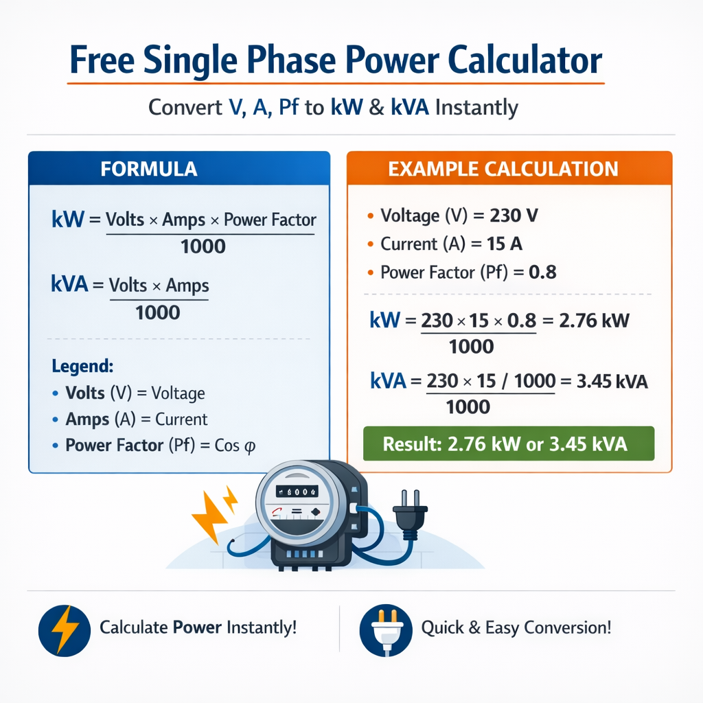
Single-Phase Power Calculator – Convert V, A and Power Factor to kW and kVA
Free Single Phase Power Calculator: convert V, A, PF to kW and kVA instantly
Accurate conversion between voltage (V), current (A), power factor (PF), kilowatts (kW) and kilovolt-amperes (kVA) is essential for load sizing, protection coordination, energy billing and power quality analysis. This article provides deterministic formulas, variable definitions, typical values, algorithmic steps for an instant calculator, extended tables with common values, and worked real-world examples with step-by-step solutions. Normative references and authoritative links are included for compliance and further reading.Fundamental equations for single-phase power conversion
Single-phase steady-state relationships use three primary quantities: - Apparent power S (in volt-amperes, VA) is the product of RMS voltage and RMS current. - Real (active) power P (in watts, W) is the portion of apparent power converted to useful work and heat. - Reactive power Q (in volt-ampere reactive, VAR) arises from phase shift between voltage and current. Key formulas (HTML format):S (VA) = V × I
P (W) = V × I × PF
Q (VAR) = V × I × sqrt(1 − PF × PF)
P (kW) = (V × I × PF) / 1000
S (kVA) = (V × I) / 1000
PF = P / S
- V — RMS voltage (volts, V). Typical single-phase nominal values: 120 V, 230 V, 240 V, 277 V, 400 V, 480 V (where two-wire single-phase is used in some systems).
- I — RMS current (amperes, A). Typical circuit currents range from fractions of an ampere (electronics) to hundreds of amperes (commercial loads).
- PF — Power factor (unitless, 0 to 1 for lagging or leading indicated as sign convention). Typical PF: 0.6–1.0 for loads; motors commonly 0.7–0.95; resistive loads PF ≈ 1.0.
- P — Real power (watts, W or kilowatts, kW). kW = W / 1000.
- S — Apparent power (volt-amperes, VA or kilovolt-amperes, kVA). kVA = VA / 1000.
- Q — Reactive power (VAR or kVAR). Useful when specifying capacitor banks for power factor correction.
Derived relations and alternative forms
When only two variables are available, derive the missing values:I = S / V
I = (P × 1000) / (V × PF)
P = sqrt(S × S − Q × Q)
Algorithm for an instant single-phase conversion calculator
A robust instantaneous converter should implement the following logic:- Input validation: Ensure V > 0, I ≥ 0, 0 < PF ≤ 1 (or allow PF = 0 for theoretical limits), and P, S non-negative.
- Detect input set: Identify which pair or single parameters are provided (V+I, V+P, P+PF, S+PF, etc.).
- Apply deterministic formula set based on inputs:
- If V and I are provided: compute S = V × I; require PF to compute P = V × I × PF.
- If V and P and PF are provided: compute I = (P × 1000) / (V × PF); compute S = V × I.
- If P and PF provided: compute S = P / PF; compute I = (S) / V.
- Round outputs to appropriate engineering precision (e.g., 3 significant figures for currents under measurement noise, two for power billing).
- Display all quantities: V, I, PF, P (W and kW), S (VA and kVA), Q (VAR and kVAR), and PF percent.
- Provide warnings if PF is outside acceptable range or if derived currents exceed conductor ratings.
Implementation hints for instant conversion
- Prefer double precision floats to reduce rounding errors for high-voltage and high-current calculations.
- Allow inputs in common units (mA, A, kA, V, kV, W, kW) and normalize internally to base units (V, A, W, VA).
- Include options for interpreting PF as leading/lagging; reactive sign affects Q sign, but magnitude formulas use sqrt(1 − PF^2).
- When PF is unknown and only V and I are available, present both extremes: P_max = V × I (if PF = 1) and indicate that real power cannot exceed S.
- Provide inverse calculators: from kW and PF to required current or conductor size with safety factors and thermal limits.
Extensive tables of common single-phase values and conversions
| Nominal Voltage (V) | Common Load Type | Example Current (A) | Apparent Power S (kVA) = V×I/1000 | Real Power P (kW) at PF=0.9 | Real Power P (kW) at PF=1.0 |
|---|---|---|---|---|---|
| 120 | Lighting / small appliances | 5 | 0.600 | 0.540 | 0.600 |
| 120 | Kitchen circuits | 20 | 2.400 | 2.160 | 2.400 |
| 230 | Residential | 10 | 2.300 | 2.070 | 2.300 |
| 230 | Heater | 16 | 3.680 | 3.312 | 3.680 |
| 240 | Air conditioner start | 30 | 7.200 | 6.480 | 7.200 |
| 277 | Commercial lighting | 8 | 2.216 | 1.994 | 2.216 |
| 400 | Industrial single-phase loads (region dependent) | 50 | 20.000 | 18.000 | 20.000 |
| 480 | Industrial equipment | 45 | 21.600 | 19.440 | 21.600 |
| Input Set | Primary Formula | Common Derived Outputs |
|---|---|---|
| V and I | S = V × I ; P = V × I × PF | S (VA/kVA), P (W/kW) with PF required, Q (VAR) if PF provided |
| P (kW) and PF | S = P / PF ; I = (S × 1000) / V | I (A), S (kVA), Q (kVAR) |
| P (kW) and V | I = (P × 1000) / (V × PF) (PF required) | I, S, Q |
| S (kVA) and PF | P = S × PF ; I = (S × 1000) / V | Real power, current |
| V and P (kW) | I = (P × 1000) / (V × PF) (requires PF) | Current, apparent power |
Practical measurement, accuracy and units handling
When building an instant calculator or performing hand calculations, observe measurement and unit details:- Always convert kW to W or kVA to VA consistently when using base formulas: multiply kW by 1000 to obtain W.
- Round intermediate results sensibly: preserve at least 3–4 significant digits for design calculations, but present final answers with user-appropriate precision.
- Account for measurement uncertainty: clamp meters, power analyzers, and true-rms meters each have specified accuracies (±1% to ±5% typical). Document measurement uncertainty when used for billing or compliance.
- For power factor correction sizing, consider harmonic distortion and filter detuning — use standards such as IEEE 519 and IEC 61000 series for harmonic limits.
Power factor nuance and reactive power sign
Reactive power Q sign convention:- Lagging PF (inductive loads) produces positive reactive VARs (Q > 0 in many conventions).
- Leading PF (capacitive) produces negative reactive VARs (Q < 0).
Q (VAR) = V × I × sqrt(1 − PF × PF)
Real-world example 1 — Residential load (resistive heater)
Problem statement: A single-phase resistive space heater is connected to a 230 V supply and draws 16 A. Determine the apparent power (kVA), real power (kW), reactive power (kVAR), and circuit current if PF is unity. Given:- V = 230 V
- I = 16 A
- PF = 1.0 (resistive)
S = V × I = 230 × 16 = 3680 VA
S (kVA) = 3680 / 1000 = 3.68 kVA
P = V × I × PF = 230 × 16 × 1.0 = 3680 W
P (kW) = 3680 / 1000 = 3.68 kW
Q = V × I × sqrt(1 − PF × PF) = 230 × 16 × sqrt(1 − 1.0 × 1.0) = 3680 × 0 = 0 VAR
So Q = 0 kVAR. 4. Interpret results:- Apparent and real power are identical for resistive loads (PF = 1).
- If sizing a breaker or conductor, check that 16 A is within allowable continuous current for the selected cable and protection device per local code (e.g., NFPA 70 / NEC for United States installations).
- S = 3.68 kVA
- P = 3.68 kW
- Q = 0 kVAR
- Circuit current I = 16 A (given)
Real-world example 2 — Industrial motor with non-unity power factor
Problem statement: An industrial single-phase motor-run load measured on site shows V = 480 V, measured current I = 45 A, measured power factor PF = 0.85 (lagging). Calculate S (kVA), P (kW), Q (kVAR), and if the motor nameplate lists 50 kW mechanical output at 92% efficiency, determine whether the electrical input power matches expectations. Given:- V = 480 V
- I = 45 A
- PF = 0.85
- Motor mechanical output (P_mech) = 50 kW
- Motor efficiency η = 0.92
S = V × I = 480 × 45 = 21600 VA
S (kVA) = 21600 / 1000 = 21.6 kVA
P = V × I × PF = 480 × 45 × 0.85 = 18480 W
P (kW) = 18480 / 1000 = 18.48 kW
Q = V × I × sqrt(1 − PF × PF) = 480 × 45 × sqrt(1 − 0.85 × 0.85)
sqrt(1 − 0.7225) = sqrt(0.2775) ≈ 0.5268
Q = 480 × 45 × 0.5268 ≈ 480 × 23.706 ≈ 11378.9 VAR
Q ≈ 11.379 kVAR
Step 4: Compare electrical input to mechanical output Electrical input real power P = 18.48 kW. If motor mechanical output is 50 kW at 92% efficiency, expected electrical input should be:P_expected = P_mech / η = 50 / 0.92 ≈ 54.3478 kW
- Measured real input (18.48 kW) is far below expected input for a 50 kW motor — this indicates either the measured load is a small motor or the system is not supplying full load to the named motor. Possible causes: measurement on a different circuit, partial loading, incorrect nameplate, or measurement error.
- The measured apparent power 21.6 kVA and PF 0.85 produce P = 18.48 kW, consistent mathematically.
- If this were the actual 50 kW motor, expected I at 480 V and PF 0.85 would be:
I_expected = (P_expected × 1000) / (V × PF) = (54.3478 × 1000) / (480 × 0.85) ≈ 133.3 A
That far exceeds the measured 45 A.
- S = 21.6 kVA
- P = 18.48 kW
- Q ≈ 11.379 kVAR
- Measured values do not match a 50 kW motor at 92% efficiency — re-check wiring and measurements.
Common practical scenarios and calculator outputs
- When given V and I but not PF: Provide S directly and warn user that P is unknown; show P ranges for PF from 0.6 to 1.0 to illustrate plausible real power range.
- When given P and PF but not V: You cannot compute I without specifying V; show I as function of selected nominal voltages (e.g., 120 V, 230 V, 480 V).
- When sizing conductors or protective devices, apply diversity, correction factors (temperature, groups), and local codes (for example, National Electrical Code in the USA).
Example: compute current required for a specified kW at different voltages
Given P = 10 kW, PF = 0.9. Compute I at V = 120 V, 230 V, and 480 V. Formula:I = (P × 1000) / (V × PF)
- At 120 V: I = (10 × 1000) / (120 × 0.9) = 10000 / 108 = 92.593 A
- At 230 V: I = 10000 / (230 × 0.9) = 10000 / 207 = 48.309 A
- At 480 V: I = 10000 / (480 × 0.9) = 10000 / 432 = 23.148 A
Standards, normative references and authoritative resources
For compliance, best practices, and deeper technical details, consult these authoritative sources:- IEC (International Electrotechnical Commission) — global electrical standards: https://www.iec.ch
- IEEE (Institute of Electrical and Electronics Engineers) — technical papers and standards on power systems and power quality: https://www.ieee.org
- NFPA 70: National Electrical Code (NEC) — wiring and protection rules (USA): https://www.nfpa.org/nec
- IEC 60038 — Standard voltages (nominal voltages): https://www.iec.ch/standards
- IEC 61000 series — Electromagnetic compatibility and power quality standards: https://www.iec.ch/standards
- IEEE Std 141 (Red Book) and IEEE Std 242 (Buff Book) — grounding and power system design guidance: https://www.ieee.org/education
- U.S. Department of Energy (DOE) — basics of electrical power, efficiency, and power factor: https://www.energy.gov
Best practices, warnings and measurement accuracy notes
- Always verify whether the system is single-phase or a split-phase derivative of a three-phase system. Misidentifying phase arrangement leads to erroneous results.
- Use true-rms meters for non-sinusoidal waveforms. Average-responding meters may report erroneous values when waveform distortion or harmonics are present.
- When performing power factor correction design, include transient loading and motor starting currents to avoid resonant conditions and overcompensation.
- For billing and contracts, ensure metering devices comply with legal metrology and revenue metering standards; small percentage errors can lead to financial disputes.
- Document measurement conditions (ambient temperature, meter accuracy class, sampling interval, load stability) to support repeatability and audits.
SEO and practical labeling for a free calculator interface
When labeling fields and outputs in a public-facing calculator, use clear, SEO-friendly field labels and affordances:- Input fields: "Voltage (V)", "Current (A)", "Power Factor (PF)", "Real Power (kW)", "Apparent Power (kVA)".
- Buttons: "Calculate kW/kVA instantly", "Convert V A PF to kW/kVA", "Clear inputs".
- Accessibility: Provide field-level help icons describing units and typical value ranges; include keyboard navigation and ARIA labels.
Summary of formula quick-reference (for UI tooltips)
| Quantity | Formula | Notes / Typical values |
|---|---|---|
| Apparent power S | S (VA) = V × I | Divide by 1000 for kVA. Typical single-phase S ranges from watts to tens of kVA. |
| Real power P | P (W) = V × I × PF | Divide by 1000 for kW. PF typically 0.6–1.0 depending on load. |
| Reactive power Q | Q (VAR) = V × I × sqrt(1 − PF × PF) | Sign depends on inductive/ capacitive nature; present as kVAR when dividing by 1000. |
| Current from P | I (A) = (P × 1000) / (V × PF) | Requires PF and voltage; useful for conductor sizing. |
- IEC — International Electrotechnical Commission: https://www.iec.ch
- IEEE — Technical resources and standards: https://www.ieee.org
- NFPA 70 (NEC) — National Electrical Code: https://www.nfpa.org/NEC
- U.S. Department of Energy — Electricity basics: https://www.energy.gov/oe/activities/technology-development/grid-modernization
- IEC 61000 Series — Power quality standards: https://www.iec.ch