Accurate UPS sizing reduces capital waste while maintaining predictable runtime and redundancy levels safely effectively.
Calculating kVA, kW, power factor and headroom avoids overbuying and ensures efficient infrastructure investment decisions.
UPS sizing calculator for IT servers (kVA, kW, power factor and headroom)
Understanding kW, kVA, and Power Factor for IT Server Loads
When sizing uninterruptible power supplies (UPS) for server environments, it is critical to distinguish between real power (kW) and apparent power (kVA). Servers draw real power measured in kilowatts (kW). UPS manufacturers rate equipment in kilovolt-amperes (kVA). The relationship between these terms is mediated by the power factor (PF):
Or, equivalently when converting to volt-amperes:
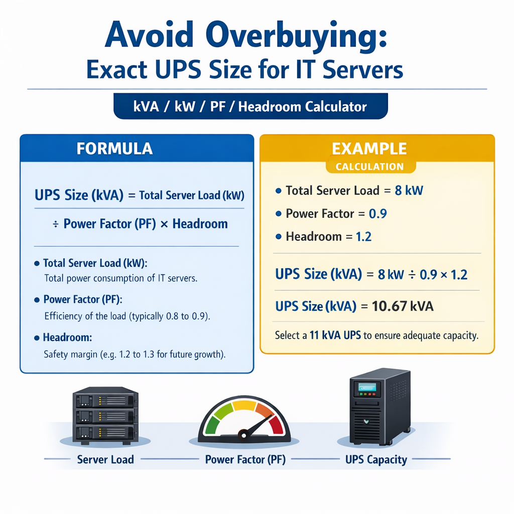
Where variables are defined and typical values are:
- kW — real power in kilowatts. Typical per-server values range from 0.1 kW (light virtualization) to 1.5+ kW (dense compute nodes).
- kVA — apparent power in kVA. UPS specs are expressed in kVA.
- PF — power factor (0–1). Typical server PF at full load: 0.9–0.98 for modern PSUs; conservative design PF: 0.9.
Why PF matters for UPS selection
UPS modules supply apparent power; if you size only to kW without PF, you may under-spec the UPS in kVA terms. Conversely, oversizing by assuming a low PF when actual PF is high leads to unnecessary capital expense.
Headroom, Safety Margins and Overbuying Risks
Headroom is the percentage margin between measured/expected load and UPS rated capacity. Correct headroom planning avoids overload while preventing overspecification.
- Typical headroom recommendation for IT racks: 10–25% depending on change rate and redundancy strategy.
- For fast-changing environments (frequent reboots, upgrades): use the upper range (20–25%).
- For static, well-inventoried deployments: 10–15% may suffice, provided monitoring and change control exist.
Overbuying occurs when designers select UPS equipment significantly larger than the actual sustained or foreseeable peak loads. Consequences include:
- Higher initial capital expenditure and larger footprint.
- Lower UPS efficiency at light load (efficiency curves often fall off below 25–30% load).
- Needlessly larger battery banks and increased maintenance costs.
Formulas and Worked Calculations
Key formulas shown using plain HTML; each is followed by variable explanations and typical example values.
Variables:
- Total_kW — summed real power of all server loads (kW).
- Headroom_fraction — decimal representation of headroom (for 20% headroom use 0.20).
- PF — expected UPS or load power factor (typically 0.9 for conservative design).
Variables:
- Battery_VA_hours — battery capacity in VA-hours (UPS vendor or battery bank spec).
- Total_kW — real load in kW.
Example typical variable values
- Small rack: 10 servers × 300 W each = 3.0 kW (PF 0.95 typical).
- Medium rack: 20 servers × 500 W each = 10.0 kW (PF 0.92).
- Data hall: 200 kW total IT load (PF 0.9 design).
- Headroom examples: 10% (0.10), 20% (0.20), 30% (0.30).
| kW Load | kVA @ PF 0.9 | kVA @ PF 0.95 |
|---|---|---|
| 1.0 kW | 1.11 kVA | 1.05 kVA |
| 3.0 kW | 3.33 kVA | 3.16 kVA |
| 5.0 kW | 5.56 kVA | 5.26 kVA |
| 10.0 kW | 11.11 kVA | 10.53 kVA |
| 20.0 kW | 22.22 kVA | 21.05 kVA |
| 50.0 kW | 55.56 kVA | 52.63 kVA |
Extensive Common-Values Tables for Quick Reference
Below are tables used by engineers when producing initial UPS size estimates. They include server types, per-unit power, and recommended headroom.
| Server Class | Typical Idle Power | Typical Full-Load Power | Typical PF | Notes |
|---|---|---|---|---|
| 1U general-purpose | 80 W | 200–400 W | 0.9–0.95 | Low density virtualization |
| 2U database server | 150 W | 400–800 W | 0.9–0.95 | High I/O systems |
| Blade chassis (per blade) | 50 W | 200–600 W | 0.85–0.95 | High density; shared cooling |
| GPU accelerated node | 300 W | 800–1500 W | 0.9–0.98 | AI/ML workloads |
| Storage array shelf | 200 W | 500–1200 W | 0.9 | Depends on disk count and controllers |
| Operational Profile | Recommended Headroom | Rationale |
|---|---|---|
| Static, controlled change window | 10% | Low variability; strong change management |
| Moderate growth, periodic refresh | 15%–20% | Plan for capacity migration and upgrades |
| Rapid growth or trial environments | 20%–30% | Frequent hardware churn; avoid emergency upgrades |
| High availability with spare modules | 10% per active module | Use N+1 or 2N strategies to size total bank |
Step-by-Step Sizing Workflow
- Inventory: measure actual installed server nameplate and measured consumption during peak periods.
- Aggregate: sum individual server kW loads (use measured values where possible).
- Apply headroom: multiply Total_kW × (1 + Headroom_fraction).
- Adjust for PF: divide adjusted kW by PF to compute required kVA.
- Select UPS: choose UPS with kVA rating >= kVA_required and verify runtime and efficiency curves.
- Verify redundancy: if N+1 or 2N is required, size modules and battery banks accordingly.
- Validate: perform commissioning tests and monitor real-world load to fine-tune future purchases.
Redundancy sizing (N+1) practical rule
When designing N+1 with modular UPS arrays, compute the required active capacity and ensure one module redundancy:
Ensure Module_capacity_kVA does not exceed individual module rating. For example, for kVA_required 60 kVA and 3 modules (N+1): Module_capacity_kVA = 60 / (3 - 1) = 30 kVA per module.
Example 1: Rack-Level Calculation — 10 x 300 W Servers (Detailed)
Scenario: one rack with 10 identical 1U servers. Each server rated at 300 W at expected operating point. The environment target headroom is 20%. Design PF conservative assumption: 0.92. Objective: choose UPS kVA to support the rack with 30 minutes runtime at rated load.
Step 1 — Total real power (Total_kW):
Step 2 — Apply headroom (20%):
Step 4 — Select typical UPS. Standard small UPS sizes: 3 kVA, 5 kVA. Choose greater or equal rating: pick 5 kVA unit. Rationale: 5 kVA provides margin for future growth and ensures UPS not operating at extremely low efficiency points.
Step 5 — Battery runtime estimate (vendor quotes batteries in minutes at given kW). Suppose the chosen 5 kVA UPS with internal battery pack provides 30 minutes at 2.5 kW; calculate required battery capacity for 3.0 kW sustained load for 30 minutes:
Assume battery invert/charger losses already accounted by vendor. Simpler approach using real power:
Commercial decision: choose 5 kVA UPS with a battery module providing ≥ 1.7 kVAh at the specified discharge profile. Confirm vendor curves for runtime at 3.0 kW load.
Example 2: Small Data Hall — 3 Racks, N+1 Modular UPS (Detailed)
Scenario: three racks each with the following mix: 20 servers at 400 W per rack, plus storage and networking equipment per rack 2.0 kW combined. Total IT load across 3 racks must be supported with N+1 modular UPS with target headroom 15%. Design PF assumption: 0.9. Objective: determine total UPS kVA, module size for N+1 with 4 modules, and battery runtime for 15 minutes.
Step 1 — Per-rack server power:
Step 2 — Total data hall kW:
Step 3 — Apply headroom 15%:
Step 5 — N+1 modular design with 4 modules (3 active + 1 spare). Compute module nominal kVA rating:
Round up to standard module sizes: typical modular UPS modules: 10 kVA, 15 kVA, 20 kVA. Choose 15 kVA modules to satisfy module_kVA requirement and provide a buffer. Total installed capacity with 4 × 15 kVA modules = 60 kVA.
Step 6 — Verify active capacity vs required kVA:
With 4 modules configured for N+1, the system can support up to 3 × 15 = 45 kVA active (since one module is spare). 45 kVA >= 38.34 kVA required — satisfies requirement and leaves incremental headroom for short-term peaks.
Step 7 — Battery sizing for 15 minutes runtime at full IT load (30 kW):
Convert to battery VAh (assuming PF 0.9 if vendor expresses VAh): Battery_VA_hours = (7.5 × 1000) / 0.9 ≈ 8333 VAh
Design decision: select battery bank sized to deliver ≥ 8.3 kVAh at the UPS specified discharge curve. Confirm charging currents, runtime derating with temperature, and spare battery capacity for aging.
Practical Considerations to Avoid Overbuying
- Use actual measured power instead of nameplate values whenever possible. Metering at PDU/rack level gives precise kW and PF.
- Right-size headroom to your operational risk appetite. Excessive headroom increases cost and lowers efficiency.
- Consider UPS efficiency curves. Many UPS efficiencies drop at light loads; oversizing can move operation into low-efficiency regions where electricity costs rise.
- Plan modular growth. Modular UPS allows incremental investment and prevents buying large monolithic systems prematurely.
- Account for derating factors: ambient temperature, altitude, harmonic distortion. For example, UPS capacity decreases with high ambient temperature — consult vendor derating curves.
- Account for inrush currents and transient loads. While kW/kVA sizing covers steady-state, ensure upstream infrastructure and UPS transfer components handle peaks.
Efficiency and utilization trade-offs
UPS systems typically have the highest efficiency between 50–75% load. Running a 30 kW load on a 100 kVA system yields poor efficiency; thus choose capacity that keeps operating point in an efficient band while maintaining required headroom and redundancy.
Verification, Monitoring and Continuous Rightsizing
Rightsizing is not a one-time exercise. Implement continuous monitoring and regular reviews.
- Deploy per-rack PDUs or smart PDUs to collect kW, kWh, and PF metrics.
- Use trending to identify growth patterns and plan UPS module additions rather than wholesale replacement.
- Perform periodic commissioning tests and load bank validation to confirm runtime predictions and battery health.
Standards, Normative References and Authority Sources
Reference the following authoritative documents and bodies when designing critical power:
- IEC 62040 series — Uninterruptible power systems (UPS) standards: functional and performance requirements. See: https://www.iec.ch
- IEEE Std 446 — Recommended Practice for Emergency and Standby Power Systems Design (Gold Book). See: https://www.ieee.org
- ASHRAE Datacom Series and TC 9.9 guidance on environmental and power design for data centers. See: https://www.ashrae.org
- Uptime Institute — Tier Standard and operational best practices for data centers. See: https://uptimeinstitute.com
- NIST and national electrical codes for electrical installation requirements and safety compliance (consult local codes). See: https://www.nist.gov
Checklist for Procurement and Specification
- Record measured kW and PF at peak and typical loads.
- Determine required headroom based on operational risk and growth plan.
- Calculate kVA requirement using kVA = (Total_kW × (1 + Headroom)) / PF.
- Select UPS modules such that planned N+1 or 2N redundancy and efficiency targets are met.
- Specify battery runtime and verify vendor runtime curves at expected load and temperature.
- Require vendor-provided efficiency curves, derating tables, and harmonic tolerance documentation.
- Ensure maintenance accessibility, spare parts strategy, and remote monitoring capabilities.
Summary of Practical Rules of Thumb
- Measure first; estimate only if metering is unavailable.
- Use PF = 0.9 for conservative initial kVA sizing if actual PF unknown.
- Apply 10–25% headroom depending on change rate and operational discipline.
- Prefer modular UPS to incremental capacity additions and to limit upfront capital expense.
- Match battery capacity to required runtime using kWh rather than VAh when possible; convert with PF if needed.
Further Reading and External Resources
For in-depth technical guidance consult:
- IEC 62040 series — https://www.iec.ch/standards
- IEEE Standards and recommended practices — https://www.ieee.org/standards
- ASHRAE Datacom resources — https://www.ashrae.org/technical-resources/datacom
- Uptime Institute — https://uptimeinstitute.com/resources
- Manufacturer application notes (APC/Schneider, Eaton, Vertiv, Stäubli) — use vendor runtime and derating documentation for final selection.
Final operational recommendation
Adopt a measurement-driven workflow, apply conservative but justifiable headroom, and favor modular UPS architectures. This approach delivers precise kVA selection, limits overbuying, preserves efficiency, and supports predictable capacity growth.