Select a common metric cable size such as 2.5, 6, 16 or 35 mm², or enter a custom area. The converter compares AWG sizes and supports larger conductors up to 2000 kcmil. A larger cross-sectional area alone does not establish cable ampacity.
Globally, engineers must match metric cable sizes with AWG standards; this guide offers formulas, tables, and examples. For current calculations, use our three-phase current calculator for kW, HP or kVA, or our kVA to amps calculator for single-phase and three-phase circuits.
mm² to AWG Converter (Wire Gauge)
How do we convert mm² to AWG?
What does “next larger area” mean?
Solid vs stranded?
Common metric cable sizes compared with AWG
Metric sizes usually fall between AWG steps. “Nearest gauge” follows the calculator’s rounded logarithmic gauge; it can have less area than the input. The last column gives the smallest listed size with at least the input area, including intermediate AWG gauges. Above 4/0, the nearest entry is compared by area within the listed kcmil sizes. Availability varies by cable type. Neither column establishes a suitable cable for an installation.
| Input mm² | Nearest gauge | Its area mm² | Size at or above input area |
|---|---|---|---|
| 1.5 | 15 AWG | 1.650 | 15 AWG (1.650 mm²) |
| 2.5 | 13 AWG | 2.624 | 13 AWG (2.624 mm²) |
| 4 | 11 AWG | 4.172 | 11 AWG (4.172 mm²) |
| 6 | 9 AWG | 6.634 | 9 AWG (6.634 mm²) |
| 10 | 7 AWG | 10.549 | 7 AWG (10.549 mm²) |
| 16 | 5 AWG | 16.773 | 5 AWG (16.773 mm²) |
| 25 | 3 AWG | 26.670 | 3 AWG (26.670 mm²) |
| 35 | 2 AWG | 33.631 | 1 AWG (42.408 mm²) |
| 50 | 1/0 AWG | 53.475 | 1/0 AWG (53.475 mm²) |
| 70 | 2/0 AWG | 67.431 | 3/0 AWG (85.029 mm²) |
| 95 | 3/0 AWG | 85.029 | 4/0 AWG (107.219 mm²) |
| 120 | 250 kcmil | 126.677 | 250 kcmil (126.677 mm²) |
Six examples: what the comparison means
- 2.5 mm²: nearest gauge 13 AWG has approximately 2.624 mm². The listed size at or above 2.5 mm² is 13 AWG, approximately 2.624 mm².
- 6 mm²: nearest gauge 9 AWG has approximately 6.634 mm². The listed size at or above 6 mm² is 9 AWG, approximately 6.634 mm².
- 16 mm²: nearest gauge 5 AWG has approximately 16.773 mm². The listed size at or above 16 mm² is 5 AWG, approximately 16.773 mm².
- 35 mm²: nearest gauge 2 AWG has approximately 33.631 mm². The listed size at or above 35 mm² is 1 AWG, approximately 42.408 mm².
- 95 mm²: nearest gauge 3/0 AWG has approximately 85.029 mm². The listed size at or above 95 mm² is 4/0 AWG, approximately 107.219 mm².
- 120 mm²: nearest listed size 250 kcmil has approximately 126.677 mm². The listed size at or above 120 mm² is 250 kcmil, approximately 126.677 mm².
For 120 mm², 4/0 AWG has only about 107.219 mm², so the calculator uses its kcmil list for the next area comparison.
From wire area to an electrical cable check
An AWG conversion answers how large a conductor is. Before choosing it for a circuit, check how much current it can carry and how much voltage is lost along the run.
- Use the wire size and ampacity calculator to compare copper or aluminum candidates using the applicable temperature rating. Account separately for terminal limits and installation corrections that the selected calculation does not cover.
- Use the voltage drop calculator by cable length and cross-sectional area with your candidate mm² size, load current and one-way route length. Do not double the entered distance when the calculator already accounts for the return conductor.
For example, a 6 mm² candidate on a short connection and the same cable on a long run have the same nominal area but different voltage drops. Passing an area comparison alone cannot settle the cable selection.
Why mm² to AWG Conversion Matters
- International projects: Engineers working across different countries need to specify cable sizes that comply with local standards.
- Equipment imports: Many machines are designed in AWG but installed in countries using mm².
- Electrical safety compliance: Correct sizing prevents overheating, voltage drop issues, and potential fire hazards.
- Compatibility: Check each terminal’s accepted conductor sizes, material and stranding class separately.
For electrical design to be safe and efficient, engineers must understand not just the conversion values, but also the current-carrying capacity and mechanical properties associated with each size.
Extended mm² to AWG Conversion Table
The chart below gives calculated areas for selected AWG and kcmil sizes. Values are rounded to three decimal places. It covers approximately 0.051 to 506.707 mm²; use the calculator for intermediate gauges and larger kcmil sizes.
Table 1 – Metric to AWG Conversion (Nominal Values)
| Wire size | Area (mm²) | Equivalent solid diameter (mm) |
|---|---|---|
| 30 AWG | 0.051 | 0.255 |
| 28 AWG | 0.081 | 0.321 |
| 26 AWG | 0.129 | 0.405 |
| 24 AWG | 0.205 | 0.511 |
| 22 AWG | 0.326 | 0.644 |
| 20 AWG | 0.518 | 0.812 |
| 18 AWG | 0.823 | 1.024 |
| 16 AWG | 1.309 | 1.291 |
| 14 AWG | 2.081 | 1.628 |
| 12 AWG | 3.309 | 2.053 |
| 10 AWG | 5.261 | 2.588 |
| 8 AWG | 8.366 | 3.264 |
| 6 AWG | 13.302 | 4.115 |
| 4 AWG | 21.151 | 5.189 |
| 2 AWG | 33.631 | 6.544 |
| 1/0 AWG | 53.475 | 8.251 |
| 2/0 AWG | 67.431 | 9.266 |
| 3/0 AWG | 85.029 | 10.405 |
| 4/0 AWG | 107.219 | 11.684 |
| 250 kcmil | 126.677 | 12.700 |
| 300 kcmil | 152.012 | 13.912 |
| 350 kcmil | 177.348 | 15.027 |
| 500 kcmil | 253.354 | 17.961 |
| 600 kcmil | 304.024 | 19.675 |
| 800 kcmil | 405.366 | 22.718 |
| 1000 kcmil | 506.707 | 25.400 |
How to read this table: kcmil rows show calculated conductor area: 1 kcmil = 0.506707479 mm². Their diameters are equivalent solid-circle diameters, not the measured diameter of a stranded or insulated cable. Nominal metric cable sizes are not exact kcmil equivalents. Verify ampacity separately using the applicable installation method, conductor material, insulation and terminal ratings, ambient temperature and grouping corrections.
For more detailed ampacity charts, consult:
Formulas for mm² to AWG Conversion
Diameter: d = 0.127 × 92(36 − n)/39 mm.
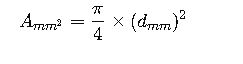
Area: A = π × d² ÷ 4 mm².
Inverse: n = 36 − 39 × ln(√(4A/π) ÷ 0.127) ÷ ln(92).
Use n = 0, −1, −2 and −3 for 1/0, 2/0, 3/0 and 4/0. The inverse can give a fractional gauge; the calculator compares whole gauges. The diameter is an equivalent solid conductor diameter, not the outside diameter of an insulated cable.
PowerStream’s wire-gauge reference gives the AWG diameter relationship. The tables here are calculated from that relationship and the circular-mil conversion.
The AWG system is logarithmic, meaning each step in gauge size corresponds to a constant factor in diameter change.
The standard mathematical relationship between AWG and diameter (inches) is:
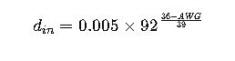
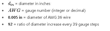
Where:
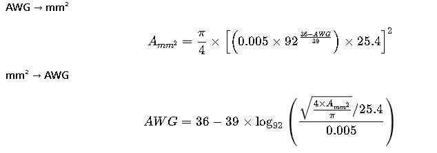
1. AWG to mm² Formula
- Convert AWG to diameter (inches):

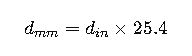
- Convert inches to millimeters:
- Calculate cross-sectional area:
2. mm² to AWG Formula
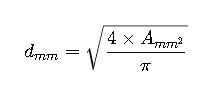
- Calculate diameter in mm:
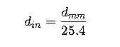
- Convert mm to inches:
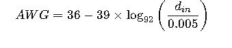
- Invert the AWG equation:
Variables Explanation
- AWG: American Wire Gauge number
- A_{mm²}: Cross-sectional area in square millimeters
- d_{mm}: Wire diameter in millimeters
- d_{in}: Wire diameter in inches
- π: Mathematical constant (~3.1416)
- 92: Scaling factor of AWG system
- 0.005 in: Diameter of AWG 36 wire
Real-World Application Examples of mm² to AWG Conversion
Example 1 – International Machine Installation
Scenario:
A U.S.-manufactured industrial packaging machine is being installed in Germany. The machine’s wiring diagram specifies 12 AWG copper conductors for the main control circuits. The German installer must choose an equivalent size in mm² to comply with local cable suppliers and IEC standards.
Step-by-Step Conversion:
1.Identify the AWG size:
The diagram specifies 12 AWG.
2.Find the equivalent mm² from the conversion formula:
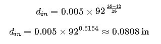
Step 1: Diameter in inches:
Step 2: Diameter in mm:

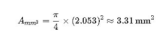
Step 3: Area in mm²:
3.Area comparison:
12 AWG ≈ 3.31 mm². A 4 mm² conductor has a larger nominal cross-sectional area. This comparison does not establish ampacity, terminal compatibility, overcurrent protection or compliance for an installation.
Application note: A larger metric area is only an area comparison. Confirm the cable specification, terminal acceptance, ampacity and applicable installation requirements before selecting a replacement.
Example 2 – Solar PV System Upgrade
Scenario:
A solar installation in California needs to upgrade from 10 AWG cables to metric equivalents because the client sources cables from a European supplier. The cable run length is 30 meters, carrying 40 A DC at 600 V.
Step-by-Step Conversion:
1.Identify the existing AWG:
10 AWG.
2.Convert AWG to mm²:
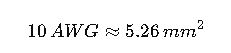
From the extended table:
3.Check ampacity separately:
A conversion from AWG to mm² does not establish the allowable current for this 40 A DC circuit. Select the applicable installation table and verify conductor material, insulation and terminal temperature ratings, ambient temperature, grouping, photovoltaic circuit requirements and overcurrent protection. Do not select a cable from nominal area alone.
4.Adjust for voltage drop:
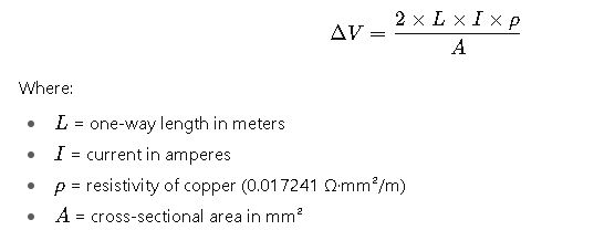
Voltage drop formula:
Calculation:

Compare the calculated voltage drop with the design criterion for the actual installation. There is no universal 3% limit covering every DC system; the percentage alone does not establish compliance.
- Conversion result:
10 AWG is approximately 5.26 mm²; 6 mm² is a larger metric area. Treat it as a candidate for a separate cable-sizing check, not as approval for the stated 40 A photovoltaic circuit.
Technical Considerations When Converting mm² to AWG
1. Tolerance and Manufacturing Variations
AWG and mm² are nominal sizes. Real wire diameters can vary due to:
- Stranding: Flexible cables have slightly larger overall diameters for the same cross-section.
- Insulation thickness: Affects fit into lugs/connectors.
- Production tolerances: Use the applicable conductor specification and manufacturer data; do not assume a universal percentage.
2. Material Conductivity
- The geometric AWG-to-area relationship does not change with conductor material.
- Copper and aluminum require separate resistance and ampacity checks. Do not apply a fixed gauge offset as a universal substitution rule.
3. Insulation Type
Current-carrying capacity depends heavily on insulation material:
- PVC: Check the marked wire type and its dry/wet temperature ratings.
- XLPE: Use the temperature rating of the specified cable construction.
- PTFE: Verify the product rating; insulation material alone does not set the allowable current.
4. Application Environment
Factors such as ambient temperature, bundling, and installation method reduce ampacity, requiring up-sizing.
5. Compliance with Standards
Two main families of standards affect sizing:
- NEC (NFPA 70) – United States
- IEC 60364 – International
Use the code edition adopted for the installation. A metric-to-AWG conversion alone does not establish compliance with either code.
Quick Reference Formula Recap
Authoritative Resources
For deeper technical validation and compliance checks: