Arc flash risk assessment requires precise incident energy calculations for safe electrical system maintenance practices.
This article examines calculators, formulas, standards, and implementation steps for accurate arc flash energy estimation.
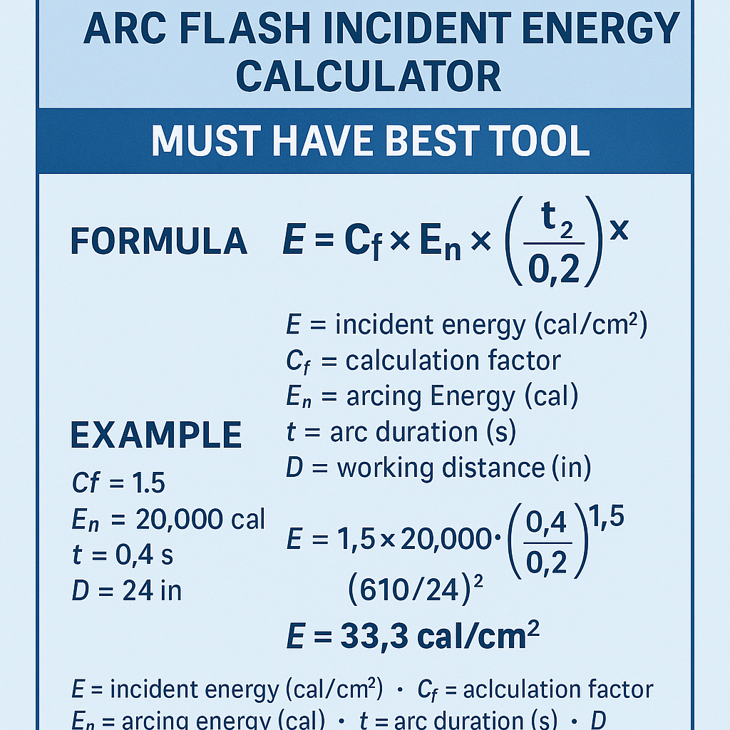
Arc Flash Incident Energy Calculator - Must Have Best Tool
Arc Flash Incident Energy: technical overview and why a calculator matters
Arc flash incident energy is the thermal energy per unit area (cal/cm2) that a worker might receive at a given working distance during an arc event. Accurate quantification is essential for selecting personal protective equipment (PPE), setting safe work boundaries, and implementing protective-device coordination to limit energy delivered to a fault.Calculating incident energy is not a trivial algebraic exercise; it relies on system topology, equipment enclosure geometry, available bolted fault current, arcing current prediction, and the clearing time of the protective device. Industry-accepted methods (notably IEEE 1584 and NFPA 70E) provide empirical models and prescriptive workflows that must be implemented in any reliable calculator.Core inputs every arc flash incident energy calculator must have
A robust calculator must accept, validate, and document the following minimum inputs:- System nominal voltage and frequency (e.g., 480 V, 60 Hz).
- Available bolted fault current at the point of work (Ibf), in kA.
- Equipment type and enclosure (e.g., open-air, enclosed switchgear, motor control center).
- Working distance (D) — distance from the arc to the worker (inches or mm).
- Protective device characteristics and operating time (breaker curve, fuse clearing time, relay operation).
- Grounding configuration, conductor sizes, and series impedance as necessary for network-level calculation.
- Ambient and transient conditions if applicable (for advanced analyses).
- Use of IEEE 1584-2018 empirical method (or later) with selectable models for different configurations.
- Automatic conversion of bolted fault current to arcing current using validated correlations by enclosure and gap.
- Device time-current curve parsing to compute accurate clearing time as a function of current.
- Ability to perform sensitivity and uncertainty analysis (e.g., ±10% fault current, device miscoordination).
- Full audit trail and exportable report with assumptions, inputs, and references to standards.
- Localization options for units (SI/imperial), languages, and standards versions.
General empirical form: incident energy relationship
Most practical calculators implement a model where incident energy scales with the square of arcing current and linearly with clearing time; it also decays with distance. A commonly used empirical representation (shown here as a conceptual model) is:E = C × I_arc2 × t / D2
Where:- E = incident energy (cal/cm2).
- C = empirical conversion constant (depends on configuration, units, and enclosure geometry).
- I_arc = arcing current (kA) — the current participating in the arc.
- t = arcing time (s) — the protective device clearing time.
- D = working distance (inches) — measured from the arc to the worker.
- This expression is a simplified representation to demonstrate scaling behavior. IEEE 1584 provides empirical logarithmic equations to calculate I_arc and the incident energy more accurately for multiple voltages and configurations; the constant C and exponents vary in the standard’s formulations.
- Any calculator intended for compliance must either implement IEEE 1584 (or recognized equivalent) directly or clearly document approximation limits and conservative assumptions.
Variable definitions and typical values used in practice
I_arc estimation
- Ibf (bolted fault current): computed from short-circuit studies or measured by network analysis. Typical low-voltage ranges: 5–50 kA for industrial distribution; medium-voltage ranges: 10–200 kA depending on utility and transformer impedance.
- Arcing current fraction (f): the ratio I_arc/I_bf is empirically derived by IEEE 1584 and depends on voltage, enclosure, and electrode gap. Typical practical fractions for planning (approximate): enclosed LV equipment 0.4–0.8; open-air arrangements 0.6–0.9.
- Working distance (D): common values — panel work 18 inches (457 mm), live-line work 36 inches (914 mm), and other distances as specified by task.
- Clearing time (t): derived from protective-device curves. Typical protective device clearing times: 0.02–0.05 s for high-speed breakers, 0.1–0.5 s for fuses and thermal-magnetic breakers depending on time-current characteristic and fault magnitude.
Extensive reference tables with common values
| Equipment Type | Typical Bolted Fault Current Range (kA) | Typical Arcing Current Fraction (I_arc / I_bf) | Common Working Distance (in) |
|---|---|---|---|
| 480 V Motor Control Center (enclosed) | 5 – 25 | 0.45 – 0.75 | 18 |
| 480 V Switchgear (enclosed) | 10 – 50 | 0.5 – 0.75 | 18 |
| 208 V Panelboards | 5 – 20 | 0.4 – 0.7 | 18 |
| Medium Voltage Outdoor (open-air) | 15 – 200 | 0.6 – 0.9 | 36 |
| Low-voltage busway (exposed) | 10 – 80 | 0.6 – 0.85 | 18 – 24 |
| Protective Device | Typical Clearing Time at High Faults (s) | Use Notes |
|---|---|---|
| Instantaneous Circuit Breaker Trip | 0.01 – 0.05 | Fast clearing; small energy if set correctly |
| Current-Limiting Fuse | 0.005 – 0.02 | Very fast at high fault currents; reduces incident energy markedly |
| Time-Delay Fuse / Thermal-Magnetic Breaker | 0.05 – 0.5 | Longer clearing time; increases incident energy |
| Relay + Breaker Coordination | 0.02 – 0.2 | Depends on relay pickup and breaker characteristics |
| PPE Category (NFPA 70E Legacy) | Approx. Incident Energy Range (cal/cm2) | Typical PPE |
|---|---|---|
| Category 0 | 0 – 0.4 | Arc-rated clothing, basic protection |
| Category 1 | 0.4 – 4 | Arc-rated shirt/pants, face shield |
| Category 2 | 4 – 8 | Arc-rated coverall/jacket, arc hood |
| Category 3 | 8 – 25 | Full arc suit, insulated gloves, hood |
| Category 4 | >25 | Specialized heavy arc suits and prohibitive controls |
Step-by-step calculator workflow (best-practice algorithm)
1. Collect and validate inputs:- Nominal voltage and primary system data, including transformer kVA and impedance.
- Bolted fault current at the equipment location via short-circuit study.
- Protective device identification and curve data (time-current characteristic, instantaneous trip, fuselet curve).
- Working distance and enclosure geometry (open, enclosed with door closed, ventilated, etc.).
- Apply IEEE 1584 empirical relations to convert bolted fault current and voltage to arcing current for the specified enclosure and gap.
- If IEEE 1584 cannot be applied (edge cases), use conservative arcing current fractions with documented justification.
- Use device time-current curves to find the operating time at the calculated arcing current. For protective devices upstream, determine which device will operate fastest at that current (smallest clearing time).
- For relay-trip systems, include relay operating time and breaker opening time.
- Use the IEEE 1584 incident energy equation, or the equivalent empirically validated model in the tool, to find E at the specified D.
- Where the tool uses simplifying formulas, apply conservative multipliers to ensure safety.
- Incident energy (cal/cm2) and corresponding PPE recommendation.
- Arc-flash boundary distance — distance at which incident energy equals 1.2 cal/cm2 or other limit.
- Assumptions and sensitivity analysis results; PDF/CSV export of the audit report.
Accuracy, verification and uncertainty management
Any high-quality calculator must include:- Verification against IEEE 1584 worked examples and published benchmark cases.
- Uncertainty quantification: show how ±10% variation in Ibf or ±20% in clearing time affects incident energy.
- Versioning and standards traceability: indicate which version of IEEE 1584 or NFPA 70E the tool implements.
Worked example 1 — 480 V MCC (enclosed) using practical approximation
Problem statement:- System: 480 V, 3-phase.
- Bolted fault current at MCC: Ibf = 20 kA.
- Equipment: Motor Control Center (enclosed).
- Working distance: D = 18 in.
- Protective device: instantaneous breaker with calculated clearing time t = 0.06 s.
- Use conservative arcing current fraction f = 0.7 (I_arc = f × I_bf).
I_arc = f × I_bf = 0.7 × 20 kA = 14.0 kA
E = C × I_arc2 × t / D2
For this example, we adopt an empirical constant C = 100 (see explanatory notes above). This constant is illustrative and conservative for enclosed low-voltage calculations in the units chosen (I in kA, D in inches, t in seconds).Step 3 — substitute values and compute:E = 100 × (14.0)2 × 0.06 / (18)2
Compute intermediate values:- (14.0)2 = 196
- Numerator = 100 × 196 × 0.06 = 100 × 11.76 = 1176
- Denominator = (18)2 = 324
- E = 1176 / 324 = 3.63 cal/cm2
- E ≈ 3.63 cal/cm2 at 18 inches.
- Per NFPA legacy PPE categories, this lies within Category 1 to 2 boundaries — the worker requires arc-rated clothing and possibly arc hood depending on company policy. Modern practice recommends direct incident energy values for PPE selection rather than legacy categories.
- If the breaker cleared in 0.03 s instead of 0.06 s, E would be halved to ≈ 1.82 cal/cm2.
- If arcing fraction were 0.8, I_arc = 16 kA, then E ≈ 100 × 256 × 0.06 / 324 = 4.74 cal/cm2.
Worked example 2 — 600 V open rack (higher energy scenario)
Problem statement:- System: 600 V, 3-phase open rack switchgear.
- Bolted fault current at location: Ibf = 35 kA.
- Working distance: D = 24 in.
- Protective device: upstream fuse with clearing time t = 0.20 s (depends on fuselet curve and fault current).
- Arcing current fraction f = 0.5 (conservative for some open arrangements).
I_arc = 0.5 × 35 kA = 17.5 kA
E = 100 × (17.5)2 × 0.20 / (24)2
Intermediate calculations:- (17.5)2 = 306.25
- Numerator = 100 × 306.25 × 0.20 = 100 × 61.25 = 6125
- Denominator = (24)2 = 576
- E = 6125 / 576 ≈ 10.63 cal/cm2
- E ≈ 10.63 cal/cm2 at 24 inches — clearly in the high energy range; requires Category 3 PPE or better, and engineering controls should be evaluated to reduce incident energy (e.g., replace fuse with current-limiting device, shorten clearing time, increase working distance, or add remote racking/inhibit).
- This scenario shows the sensitivity of incident energy to clearing time and highlights why device selection (e.g., use of current-limiting fuses or instantaneous trip settings) can be the most effective mitigation.
Practical mitigation strategies illustrated by calculator outputs
If a calculator reports an unacceptable incident energy, typical mitigation options include:- Decrease clearing time: reconfigure protective devices to trip faster (instantaneous trip elements, current-limiting fuses).
- Reduce arcing current: add upstream series impedance (transformer impedance selection), bus segmentation, or current-limiting devices.
- Increase working distance: adopt remote operation, extended tools, or barrier systems.
- Administrative controls: lockout/tagout, energized work policies to avoid routine energized operations where feasible.
- PPE upgrade: select certified arc-rated PPE with rating ≥ calculated incident energy plus safety margin.
Reporting, documentation, and compliance checklist
Every incident energy calculation must produce a traceable report that includes:- All input data and their sources (short-circuit study, utility data, device manufacturers).
- Standards and versions used (IEEE 1584-2018, NFPA 70E 2024, IEC 61482 reference if applicable).
- Calculation method: equation references, approximations, and conservative assumptions.
- Calculated incident energy values, arc-flash boundary, PPE recommendations, and mitigation suggestions.
- Sensitivity analysis results showing how changes in inputs affect outcomes.
Regulatory and normative references (authoritative)
- IEEE 1584™—Guide for Performing Arc-Flash Hazard Calculations: primary empirical method for arcing current and incident energy calculations. Official reference: https://standards.ieee.org/standard/1584-2018.html
- NFPA 70E: Standard for Electrical Safety in the Workplace — requirements for risk assessment, PPE, and hazard analysis. Official reference: https://www.nfpa.org/70E
- IEC 61482: Protective clothing against the thermal hazards of an electric arc — test methods and performance specifications. Overview: https://www.iec.ch
- U.S. Occupational Safety and Health Administration (OSHA) — electrical safety guidance and PPE responsibilities: https://www.osha.gov/etools/electrical
- IEEE 1584 implementation notes and example calculations published by industry training providers and technical committees (use to verify own tool outputs).
- Manufacturer time-current curve data and fuselet catalogs — always use the latest manufacturer data to determine clearing times precisely.
Validation, test cases and QA for calculator developers
To ensure a calculator is fit for purpose:- Create unit tests using benchmark examples published by IEEE 1584 and NFPA 70E annexes.
- Compare outputs with established commercial arc-flash calculators and with independent hand calculations for simplified cases.
- Include edge-case validation: zero or near-zero impedance, extremely fast protection, extremely long clearing times, and multiple protective devices.
- Maintain a change-log whenever algorithm, constants, or standard implementations are updated; offer backward compatibility or clear migration notes.
User experience, UI and data integrity considerations
A calculator’s UI should:- Guide users to enter required data with mandatory field validation and unit conversions on-the-fly.
- Show warnings where inputs are missing or inconsistent (e.g., device curve not provided for selected breaker).
- Provide defaults that are conservative and document their provenance (e.g., default arcing fractions only for preliminary screening).
- Offer batch processing for large systems, with mapping to single-line diagrams and device databases.
Summary of best-practice features — checklist for selecting the best tool
- Standards-compliant engine (IEEE 1584 implementation) with version control.
- Device curve parsing and automated clearing-time determination.
- Full audit trail, report export, and override explanation fields.
- Sensitivity and uncertainty analysis built-in.
- Secure, validated data storage and multi-user workflow for engineering teams.
- Clear guidance on assumptions, conservative defaults, and when to escalate to detailed study.
Final engineering considerations and safe-practice reminders
- Default to conservative assumptions when input data are uncertain. Err on the side of larger incident-energy estimates if sources conflict.
- Use incident energy values directly for PPE selection. Avoid relying solely on legacy “PPE category” tables unless they are explicitly aligned with the incident energy methodology used.
- Perform periodic re-evaluation of arc-flash assessments after system changes: transformer swaps, changes in utility source, or protective-device replacements.
- Train staff on interpretation of reports, limitations of models, and the difference between approximate screening calculations and full IEEE 1584-compliant studies.
- IEEE 1584™-2018 Guide for Performing Arc-Flash Hazard Calculations — the primary empirical method for arc flash hazard analysis: https://standards.ieee.org/standard/1584-2018.html
- NFPA 70E Standard for Electrical Safety in the Workplace — risk assessment and PPE requirements: https://www.nfpa.org/70E
- OSHA — Electrical safety eTool and guidance pages: https://www.osha.gov/etools/electrical
- IEC 61482 — protective clothing against arc thermal hazards: https://www.iec.ch