This guide provides precise methods to determine breaker sizes from watts, kW, and DC applications.
It covers single phase, three phase, power factor, and equipment thermal considerations worldwide and standards.Breaker Size Calculator – Determine IEC/UL Breaker Rating From Power, Voltage, DC / 1-Phase / 3-Phase and Power Factor
Fundamental electrical relationships for breaker sizing
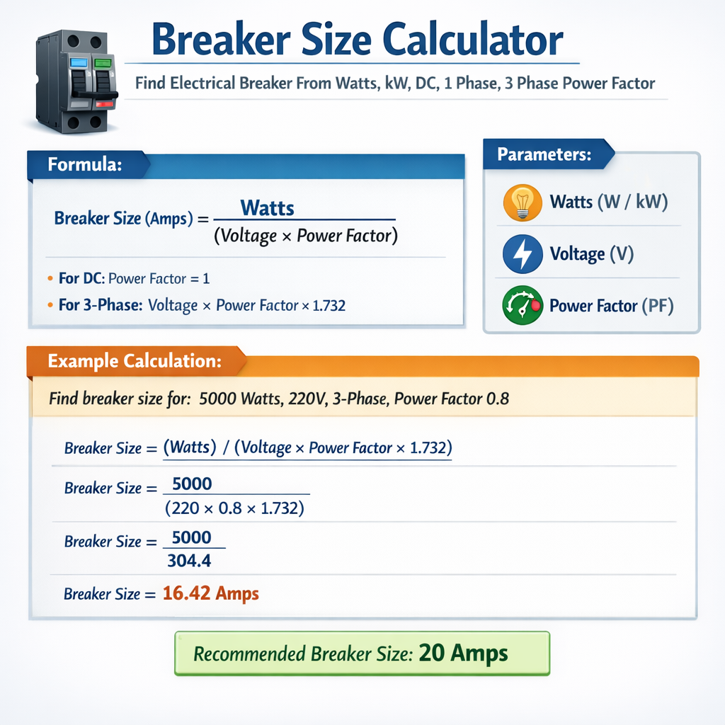
Breaker sizing begins with converting supplied power into steady-state current. Use these fundamental formulas depending on system type:
Variable definitions and typical values
- P — Real power in watts (W) or kilowatts (kW). Typical conversion: kW = W / 1000. Example: 5000 W = 5 kW.
- V — Line-to-line voltage for three-phase or line-to-neutral for single-phase. Typical values: single-phase 120 V, 230 V, 240 V; three-phase 208 V, 400 V, 415 V, 480 V; DC common systems 12 V, 24 V, 48 V, 110 V, 400–600 V for storage/inverters.
- PF — Power factor (unitless), the ratio of real power to apparent power. Typical ranges: resistive loads PF ≈ 1.0, commercial loads PF 0.8–0.95, motors 0.7–0.95 depending on loading and PF correction.
- √3 — Square root of three (approx. 1.732), used for three-phase balanced power calculations.
- I — Current in amperes (A). This is the continuous or steady-state operating current before applying protection selection rules and safety margins.
Example values: PF = 1.0 for heaters, PF = 0.9 typical for industrial three-phase motors under partial load, PF = 0.85 for mixed loads without correction.
Regulatory and practical rules for breaker selection
After calculating the load current, apply regulatory and practical rules to select a breaker rating that ensures safe operation and coordination with conductors:
- Continuous loads: Many codes (for example NFPA 70 / NEC) require sizing overcurrent protection and conductors at 125% of the continuous load current. Continuous = expected to run for 3 hours or more.
- Non-continuous loads: For non-continuous loads, sizing is typically 100% of running current unless specific code requires otherwise.
- Conductor ampacity: Choose conductor ampacity ≥ breaker rating and typically sized using thermal correction and NEC tables.
- Standard breaker sizes: Select the next standard commercial breaker rating equal to or greater than the required ampacity (examples: 15, 20, 25, 30, 40, 50, 60, 70, 80, 100, 125, 150 A, etc.).
- Interrupting rating (AIC/IMA): Breaker interrupting capacity must exceed the available fault current at point of installation.
- Temperature derating: Adjust conductor ampacity for ambient temperature and grouping per code.
- Motor loads: Motor branch-circuit and short-circuit protection follow special tables and rules (e.g., NEC motor branch-circuit sizing uses motor nameplate FLC and specific percentages for overload and short-circuit protection).
Safety and DC-specific considerations
- DC breakers and fuses require higher interrupting capacity because DC has no natural current zero crossing; contacts and arc suppression must be designed accordingly.
- DC voltage rating of the breaker must exceed system voltage; choose equipment rated for DC use (e.g., 48 VDC, 250 VDC, 600 VDC ratings).
- Sizing conductors for DC systems must account for continuous current and ambient conditions similar to AC systems; follow manufacturer and standard guidance.
- Coordination: Verify selective coordination with upstream and downstream devices for selective tripping where required.
Standard formulas applied with code multipliers
To convert calculated current to a breaker size compliant with common code practices, use the following steps:
- Calculate I_load using the appropriate formula above for single-, three-phase, or DC.
- If load is continuous, calculate I_adjusted = I_load × 1.25 (125% rule).
- Select the next higher standard breaker rating B such that B ≥ I_adjusted.
- Verify conductor ampacity ≥ B (or apply conductor rules which sometimes require conductor ampacity ≥ I_load × 125% rather than breaker rating depending on jurisdiction).
- Confirm breaker and conductor interrupting and voltage ratings exceed available fault current and system voltage.
Formula examples with variable explanations
Variables: P in watts (W). V in volts (V). PF in decimal (0–1). Example typical values: P = 2400 W, V = 240 V, PF = 1.0.
Variables: P in watts (W). V = line-to-line voltage (V). PF = power factor. √3 ≈ 1.732. Example typical values: P = 100000 W (100 kW), V = 480 V, PF = 0.9.
Variables: P in watts. V in volts DC. Example: P = 5000 W, V = 48 V -> I = 104.17 A.
Extensive tables: common kW to amps for typical voltages
| kW | Single-phase 120 V (A) | Single-phase 230 V (A) | Single-phase 240 V (A) | Three-phase 208 V (A) | Three-phase 400 V (A) | Three-phase 480 V (A) | DC 48 V (A) |
|---|---|---|---|---|---|---|---|
| 0.5 | 4.17 | 2.17 | 2.08 | 1.39 | 0.72 | 0.60 | 10.42 |
| 1 | 8.33 | 4.35 | 4.17 | 2.78 | 1.44 | 1.20 | 20.83 |
| 2 | 16.67 | 8.70 | 8.33 | 5.56 | 2.88 | 2.40 | 41.67 |
| 5 | 41.67 | 21.74 | 20.83 | 13.89 | 7.21 | 6.00 | 104.17 |
| 10 | 83.33 | 43.48 | 41.67 | 27.78 | 14.43 | 12.00 | 208.33 |
| 25 | 208.33 | 108.70 | 104.17 | 69.44 | 36.07 | 30.00 | 520.83 |
| 50 | 416.67 | 217.39 | 208.33 | 138.89 | 72.14 | 60.00 | 1041.67 |
| 100 | 833.33 | 434.78 | 416.67 | 277.78 | 144.29 | 120.00 | 2083.33 |
Notes: Single-phase currents assume PF = 1. Three-phase currents shown are for balanced loads and PF = 1. For PF < 1, divide currents by PF (i.e., currents increase).
| kW | Three-phase 380 V (A) PF=0.9 | Three-phase 415 V (A) PF=0.9 | Three-phase 600 V (A) PF=0.9 |
|---|---|---|---|
| 10 | 16.0 | 14.6 | 10.6 |
| 25 | 40.0 | 36.4 | 26.6 |
| 50 | 80.0 | 72.8 | 53.2 |
| 100 | 160.0 | 145.7 | 106.6 |
| 250 | 400.0 | 364.3 | 266.6 |
| 500 | 800.0 | 728.6 | 533.3 |
Standard breaker sizes and selection guidance
After computing required current, select a breaker from standard nominal ratings. Common single-pole and multi-pole breaker nominal ratings in amps include:
- Low range: 10 A, 15 A, 20 A, 25 A, 30 A, 35 A, 40 A
- Medium range: 45 A, 50 A, 60 A, 70 A, 80 A, 90 A, 100 A
- Large range: 125 A, 150 A, 175 A, 200 A, 225 A, 250 A, 300 A, 400 A, 600 A
Selection example rule-of-thumb: If I_adjusted = 52 A (continuous), choose the next standard breaker ≥52 A, typically 60 A. Then verify conductor ampacity meets code requirements and temperature derating.
Overcurrent device rating vs conductor ampacity
- NEC typical rule: For continuous loads, conductor ampacity must be ≥ 125% of continuous load current. Overcurrent protective device can be sized based on allowable next-higher standard size rules in article 240.4 and 240.6 (consult local code).
- Acceptable practice: Evaluate both conductor ampacity and breaker pickup curves, and perform short-circuit and selectivity coordination analysis if installed in distribution systems.
Detailed worked examples
Case 1 — Single-phase resistive heater: 5 kW at 240 V, continuous
Step 1 — Calculate steady-state current:
I_load = P / (V × PF) where PF = 1 for resistive heater.
Step 2 — Apply continuous load multiplier (125%):
Step 3 — Select standard breaker size:
Next standard common breaker ≥ 26.041 A is 30 A.
Step 4 — Verify conductor ampacity and installation rules:
- Conductor ampacity must be ≥ 26.041 A. Typical choice: 10 AWG copper THHN (30 A ampacity depending on insulation and ambient) or 12 AWG (20 A typical — insufficient).
- Therefore choose 10 AWG copper conductor and 30 A breaker.
- Confirm branch-circuit overcurrent device interrupting rating and manufacturer guidance.
Final selection: 30 A breaker, 10 AWG copper conductors, 240 V rated breaker and wiring, verify local code compliance.
Case 2 — Three-phase industrial load: 150 kW at 480 V, PF = 0.9, non-continuous
Step 1 — Calculate line current for three-phase:
Step 2 — Determine continuous vs non-continuous:
If installation is non-continuous (e.g., process intermittent), the 125% multiplier may not be required. If continuous, apply 1.25.
Assume non-continuous for this case: I_adjusted = I_load = 200.43 A.
Step 3 — Select standard breaker:
Next standard breaker ≥ 200.43 A is typically 225 A (some panels offer 200 A, but manufacturer standard sizes often 225 A). Choose 225 A breaker.
Step 4 — Verify conductor sizing:
- Conductor ampacity must be ≥ 200.43 A if non-continuous — choose conductor per table (e.g., 3/0 AWG copper THHN has ampacity of ~200–225 A depending on conditions; 4/0 may be used for margin).
- If continuous, apply 125%: 200.43 × 1.25 = 250.54 A -> breaker selection 300 A (or per allowed rounding rules), conductor accordingly.
- Confirm short-circuit current interruptions (AIC) rating of the selected breaker meets available fault current at the switchboard.
Final selection: For non-continuous, choose 225 A breaker with appropriate conductor (e.g., 3/0 or 4/0 copper based on ambient and derating), confirm coordination and AIC.
Case 3 — DC battery bank and inverter: 5 kW DC load at 48 V (continuous)
Step 1 — Calculate DC current:
Step 3 — Select DC-rated overcurrent device:
- Choose a DC-rated breaker or fuse with voltage rating ≥ system voltage (e.g., 150 VDC rating provides safety margin; many DC breakers are specified at 48 VDC or 1000 VDC — choose appropriate type).
- Standard breaker sizes: next common rating ≥130.208 A is typically 150 A.
- Confirm the breaker is rated for DC operation at 48 V and has suitable interrupting capacity for available fault current.
Step 4 — Conductor sizing:
- Conductor ampacity must be ≥130.208 A. Typical selection: 2/0 AWG copper or parallel conductors depending on installation and table values, with temperature corrections applied.
- Consider inrush and startup currents if connected to battery inverters and switching transient suppression.
Final selection: DC-rated 150 A breaker, conductor sized for ≥130 A continuous, verify manufacturer recommendations and DC arc suppression capability.
Other practical considerations and advanced topics
Power factor and apparent power
When PF < 1, the apparent power S in volt-amperes rises: S = P / PF. Overcurrent protective devices and conductors must be sized based on real current associated with apparent power. Use formulas above with PF factor applied.
Short-circuit and interrupting capacity
Always ensure the selected breaker’s interrupting capacity (AIC or kA at specified voltage) is greater than the available prospective short-circuit current at the installation point. This typically requires a short-circuit study or reference to utility available fault current tables.
Selective coordination and trip curves
For facility distribution, coordinate breaker trip characteristics (instantaneous, short-time, long-time, thermal elements) to ensure selectivity and minimize outage domains. Use manufacturer time-current curves to design coordination.
Ambient temperature and derating
Conductor ampacities and sometimes breaker trip characteristics are affected by ambient temperatures and grouping. Always apply derating factors per applicable standards: NEC tables for conductor temperature correction and bundling.
Normative references and authoritative resources
- NFPA 70, National Electrical Code (NEC) — essential US code for overcurrent protection, conductor ampacity, and branch-circuit requirements. https://www.nfpa.org/NEC
- IEC 60947 series — low-voltage switchgear and controlgear (circuit-breaker requirements for international practice). https://www.iec.ch
- UL 489 — Standard for Molded-Case Circuit Breakers, for product testing and certification. https://standardscatalog.ul.com
- IEEE standards for power system studies and coordination (selective coordination, short-circuit calculations). https://www.ieee.org
- Manufacturer technical resources: Schneider Electric, Siemens, Eaton — product datasheets for breaker voltage, current, and interrupting ratings.
- NEMA publications on enclosure and electrical equipment ratings. https://www.nema.org
Checklist for correct breaker sizing and installation
- Identify load type: resistive, motor, inverter, mixed.
- Measure or compute steady-state real power P (W or kW).
- Select correct formula for single-phase, three-phase, or DC.
- Apply power factor where applicable.
- Apply continuous load multiplier (typically 125%) if applicable.
- Choose next higher standard breaker rating.
- Verify conductor ampacity, temperature derating, and grouping rules.
- Check breaker voltage and interrupting rating against available fault current.
- For motors and certain loads, follow specific branch-circuit rules and tables.
- Document selection, provide manufacturer datasheets, and perform on-site verification.
SEO-focused keywords and summary guidance for engineers
Keywords to index effectively: breaker size calculator, find breaker from watts, kW to breaker, DC breaker sizing, single phase breaker calculation, three phase breaker calculation, power factor breaker sizing, NEC breaker sizing rules.
In practice, use a verified breaker size calculator that implements these formulas, code multipliers, and standard size tables, but always validate results against local code, short-circuit studies, and manufacturer limits. Engineer judgment must account for system-specific factors such as inrush, ambient temperature, conductor terminations, and maintenance coordination.
References
- National Fire Protection Association, NFPA 70: National Electrical Code. https://www.nfpa.org/NEC
- International Electrotechnical Commission (IEC) standards catalog. https://www.iec.ch
- UL Standards Directory (e.g., UL 489). https://standardscatalog.ul.com/standards/en/standard_489
- IEEE Xplore digital library for equipment coordination and fault current analysis. https://ieeexplore.ieee.org
- Manufacturer technical resources (example): Schneider Electric circuit breaker selectors. https://www.se.com
Use these formulas, tables, regulatory references, and worked examples as an authoritative technical approach to convert watts or kW into an appropriate breaker selection for single-phase, three-phase, and DC systems while observing power factor and continuous load rules.