Electrical engineering and electronics depend on accurate conversion between volts and amperes to ensure system safety. A volts-to-amperes calculator provides quick current determination, guiding engineers, technicians, electricians, and everyday equipment users.
Watts ↔ Amperes Calculator
Understanding the Relationship Between Volts and Amperes
- Voltage (V): Represents electrical potential difference, measured in volts.
- Current (I): Represents the flow of electric charge, measured in amperes (A).
- Power (P): The rate at which energy is transferred or consumed, measured in watts (W).
- Resistance (R): The opposition to current flow, measured in ohms (Ω).
The core relationship is described by Ohm’s Law and the Power Law.
Fundamental Formulas
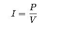
1. Ohm’s Law

Where:
- I= Current (Amperes, A)
- V= Voltage (Volts, V)
- R= Resistance (Ohms, Ω)
Common resistance values in electronics:
- Resistors: 1 Ω – 10 MΩ
- Household appliances: 5 – 100 Ω
- Heating elements: 10 – 1000 Ω
2. Power Law
Where:
- P= Power (Watts, W)
- V= Voltage (Volts, V)
- I= Current (Amperes, A)
Rearranged to find current:
This is the most commonly used formula in volts-to-amperes calculators, especially when dealing with electrical appliances where wattage and voltage are known.
3. Combined Formula with Resistance
By combining Ohm’s Law and Power Law, we obtain:
This is less commonly used in calculators but is critical in design and engineering analysis.
4. AC Power Formula (with Power Factor)
For alternating current (AC) systems:
Where:
- PF = Power Factor (0 – 1).
Typical values: - Resistive loads (heaters, incandescent lamps): PF ≈ 1
- Inductive loads (motors, transformers): PF = 0.7 – 0.95
- Electronic devices with SMPS: PF = 0.6 – 0.9 (unless power factor corrected).
Extensive Volts to Amperes Conversion Tables
The following tables provide pre-calculated conversions for common voltages and power ratings. These values are essential for electricians and engineers working with real-world devices.
Table 1: Current from Voltage and Power (DC or AC with PF = 1)
| Voltage (V) | 10 W | 50 W | 100 W | 200 W | 500 W | 1000 W | 2000 W |
|---|---|---|---|---|---|---|---|
| 5 V | 2 A | 10 A | 20 A | 40 A | 100 A | 200 A | 400 A |
| 12 V | 0.83 A | 4.2 A | 8.3 A | 16.7 A | 41.7 A | 83.3 A | 167 A |
| 24 V | 0.42 A | 2.1 A | 4.2 A | 8.3 A | 20.8 A | 41.7 A | 83.3 A |
| 48 V | 0.21 A | 1.0 A | 2.1 A | 4.2 A | 10.4 A | 20.8 A | 41.7 A |
| 120 V | 0.08 A | 0.42 A | 0.83 A | 1.7 A | 4.2 A | 8.3 A | 16.7 A |
| 230 V | 0.04 A | 0.22 A | 0.43 A | 0.87 A | 2.2 A | 4.3 A | 8.7 A |
| 400 V | 0.025 A | 0.125 A | 0.25 A | 0.5 A | 1.25 A | 2.5 A | 5 A |
Table 2: Current from Voltage and Resistance (Ohm’s Law)
| Voltage (V) | 1 Ω | 5 Ω | 10 Ω | 50 Ω | 100 Ω | 500 Ω | 1000 Ω |
|---|---|---|---|---|---|---|---|
| 5 V | 5 A | 1 A | 0.5 A | 0.1 A | 0.05 A | 0.01 A | 0.005 A |
| 12 V | 12 A | 2.4 A | 1.2 A | 0.24 A | 0.12 A | 0.024 A | 0.012 A |
| 24 V | 24 A | 4.8 A | 2.4 A | 0.48 A | 0.24 A | 0.048 A | 0.024 A |
| 48 V | 48 A | 9.6 A | 4.8 A | 0.96 A | 0.48 A | 0.096 A | 0.048 A |
| 120 V | 120 A | 24 A | 12 A | 2.4 A | 1.2 A | 0.24 A | 0.12 A |
| 230 V | 230 A | 46 A | 23 A | 4.6 A | 2.3 A | 0.46 A | 0.23 A |
| 400 V | 400 A | 80 A | 40 A | 8 A | 4 A | 0.8 A | 0.4 A |
Table 3: AC Current with Power Factor (Example PF = 0.8)
| Voltage (V) | 100 W | 500 W | 1000 W | 2000 W | 5000 W |
|---|---|---|---|---|---|
| 120 V | 1.04 A | 5.21 A | 10.4 A | 20.8 A | 52.1 A |
| 230 V | 0.54 A | 2.7 A | 5.4 A | 10.8 A | 27.1 A |
| 400 V | 0.31 A | 1.56 A | 3.13 A | 6.25 A | 15.6 A |
Importance of Accurate Volts-to-Amperes Conversion
Errors in voltage-to-current calculations can cause:
- Overheating of wires and devices → risk of fire.
- Undersized fuses or breakers → nuisance tripping.
- Oversized protection devices → failure to protect equipment.
- Improper equipment selection → reduced efficiency and lifespan.
For compliance, engineers often refer to standards such as:
- IEC 60364 (Low-voltage electrical installations)
- NEC (NFPA 70) – National Electrical Code (USA)
- IEEE Std 141 – Electric Power Distribution for Industrial Plants
Practical Real-World Applications of Volts to Amperes Conversion
While tables and formulas are essential, their true value emerges when applied to real-world scenarios. Below are two detailed examples where volts-to-amperes calculations play a critical role in engineering and everyday life.
Case Study 1: Residential Water Heater Sizing
Scenario:
A homeowner in the United States installs a 4,500 W electric water heater. The supply is 240 V AC. The installer must determine the current draw to select the correct circuit breaker and wire gauge.
Step 1 – Formula:
Since resistive heating elements have a power factor ≈ 1, the formula simplifies to:
Step 2 – Substitution:
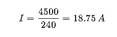
Step 3 – Engineering Considerations:
- NEC (National Electrical Code) requires that continuous loads be derated to 125%.
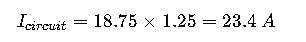
- The closest standard breaker rating above 23.4 A is 25 A, but NEC dictates using 30 A with 10 AWG copper wire.
Final Answer: The 4,500 W water heater draws 18.75 A, requiring a 30 A breaker and 10 AWG wiring.
Key Insight: This example illustrates how a simple volts-to-amperes calculation directly informs safe and compliant residential installations.
Case Study 2: Industrial Three-Phase Motor
Scenario:
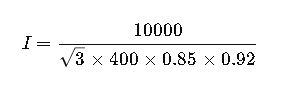
An industrial facility operates a 10 kW three-phase induction motor at 400 V AC, 50 Hz, with a power factor of 0.85 and an efficiency of 92%. The engineer must calculate the line current.
Step 1 – Formula (Three-Phase Current):
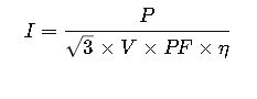
Where:
- P= Power (W)
- V = Line Voltage (V)
- PF= Power Factor
- η= Efficiency (decimal)
Step 2 – Substitution:
Step 3 – Calculation:
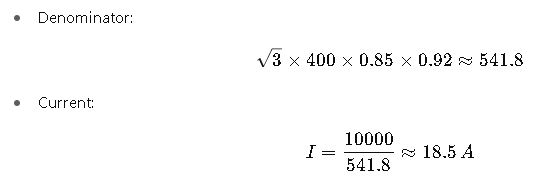
Final Answer: The motor draws 18.5 A per phase.
Engineering Implications:
- Cable sizing must consider ambient temperature and installation method (IEC 60364 guidance).
- Protection requires an overload relay calibrated slightly above 18.5 A.
- Inrush current may be 5–7× higher than full-load current, requiring motor-starting strategies (soft starters, VFDs).
Key Variables in Volts-to-Amperes Conversion
For precision, let’s expand on each influencing factor:
- Voltage (V):
- Residential supply: 120 V (North America), 230 V (Europe, Asia).
- Industrial supply: 400 V three-phase (Europe), 480 V three-phase (North America).
- Automotive: 12 V or 24 V DC.
- Current (I):
- Measured with ammeters or clamp meters.
- Critical for thermal protection and conductor sizing.
- Power (P):
- Resistive devices = Nameplate power ≈ true power.
- Inductive devices = Apparent power must be corrected by PF.
- Power Factor (PF):
- Determined by load type.
- Poor PF increases current draw without increasing useful power.
- Efficiency (η):
- Always less than 1.
- Motors: 90–98%.
- Transformers: 95–99%.
- Electronics: 70–95% depending on design.
Why Converting Volts to Amperes Matters
- Electrical Safety: Prevents overheating of cables and fire risks.
- Energy Efficiency: Avoids unnecessary current draw in industrial settings.
- System Design: Ensures proper selection of circuit breakers, contactors, fuses.
- Compliance: Meets legal standards like NEC (US), IEC (Europe), and IEEE