This guide calculates generator full load current accurately for kW and kVA to amps instantly.
Covers single-phase and three-phase systems, power factor, efficiency, formulas, tables, and worked examples with calculations.Instant Generator Full-Load Current Calculator — kW / kVA to Amps (1‑Phase & 3‑Phase)
Scope and purpose of the calculator methodology
This technical article explains the electrical formulas and practical corrections required to convert generator nameplate power (kW or kVA) to full load current (amps) for single-phase and three-phase systems.
It is written for electrical engineers, commissioning technicians, procurement specialists and site planners who require precise ampacity estimates for wiring, protection, and switchgear selection.
Fundamental relationships: kW, kVA, current and power factor
Core physical relationships
Electric power has two principal measures relevant to generators: apparent power (kVA) and real power (kW). The relationship between them uses the power factor (PF).
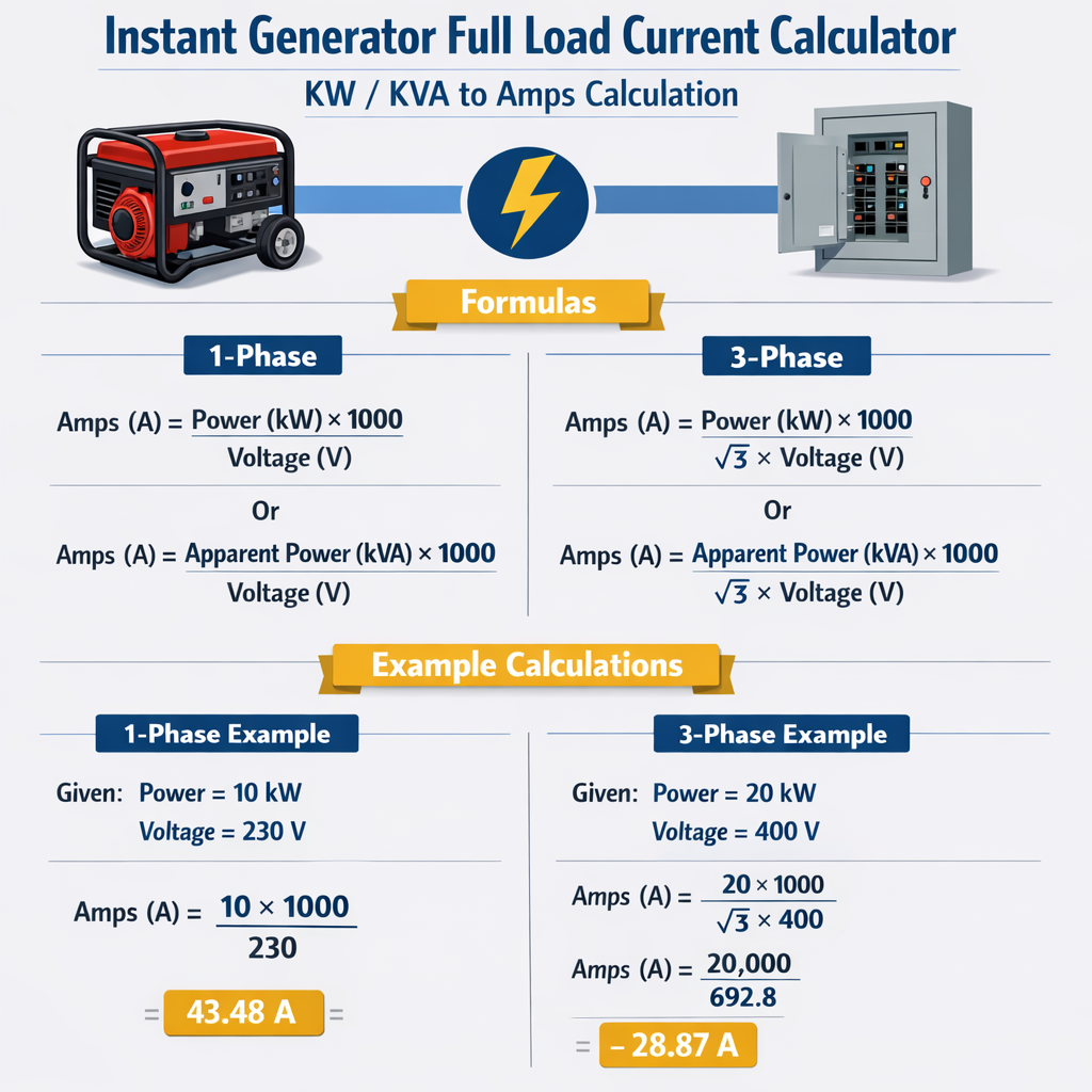
Key formulas (expressed in plain HTML):
Single-phase from kW:
I = (kW * 1000) / (V * PF)
Single-phase from kVA:
I = (kVA * 1000) / V
Three-phase from kW:
I = (kW * 1000) / (sqrt(3) * V * PF)
Three-phase from kVA:
I = (kVA * 1000) / (sqrt(3) * V)
Where sqrt(3) is 1.7320508075688772 (commonly approximated as 1.732).
Variable definitions and typical values
- I = Line current, amperes (A).
- kW = Real power delivered, kilowatts (kW). Typical generator continuous ratings use kW.
- kVA = Apparent power rating, kilovolt-amperes (kVA). Generators are often rated in kVA.
- V = Line-to-line voltage for three-phase systems, or line voltage for single-phase systems (volts, V). Common values: single-phase 120/240 V, 230 V; three-phase 208 V, 400 V, 415 V, 480 V.
- PF = Power factor (unitless). Typical assumed design PF values: 0.8 (inductive industrial loads), 0.9 (mixed loads), 1.0 (pure resistive). Many generator manufacturers assume PF = 0.8 for standby ratings.
- sqrt(3) = 1.732 (used in three-phase power conversion).
Derivation and reasoning for each formula
Single-phase derivation
If given kVA, S = kVA * 1000, hence I = S / V = (kVA * 1000) / V.
If given kW (real power), P = V * I * PF, therefore I = P / (V * PF) = (kW * 1000) / (V * PF).
Three-phase derivation
From kW: real power P = sqrt(3) * V * I * PF, hence I = (kW * 1000) / (sqrt(3) * V * PF).
Practical corrections and considerations for generator full load current
- Use the correct voltage basis: for three-phase use line-to-line voltage, not phase-to-neutral unless calculating phase currents in specific delta/wye connection scenarios.
- Use nameplate PF when converting kVA to kW or vice versa; if unknown, use a conservative PF of 0.8 for standby sizing per many manufacturers.
- Account for continuous vs standby ratings: continuous ratings may be different from emergency/standby ratings (consult ISO 8528 and NFPA 110).
- Derating for altitude and ambient temperature: generators lose capacity at high altitude and high temperature (see ISO 8528-1 guidance).
- Consider inrush currents for motors and large inductive loads: full-load steady-state currents differ from starting currents, which may be 6–10 times motor locked-rotor current.
- Protection and cable sizing must consider conductor ampacity, grouping, and corrective factors per NEC (NFPA 70) or applicable local codes.
Extensive tables: common generator sizes, voltages and calculated full load currents
The following tables provide typical conversions for both kW and kVA into full load current for common voltages and PF values. Use these for quick reference during selection and preliminary design. Values rounded to two decimals.
| Rating | Voltage (V) | PF | kVA → I (A) | kW → I (A) |
|---|---|---|---|---|
| 10 kVA | 230 | 1.00 | 43.48 | 43.48 (kW=10) |
| 10 kVA | 230 | 0.8 | 43.48 | 54.35 (kW=8) |
| 20 kVA | 230 | 1.00 | 86.96 | 86.96 |
| 20 kVA | 230 | 0.8 | 86.96 | 108.70 |
| 15 kVA | 240 | 1.00 | 62.50 | 62.50 |
| 15 kVA | 240 | 0.8 | 62.50 | 78.13 |
| 50 kVA | 400 | 1.00 | 72.17 | 72.17 |
| 50 kVA | 400 | 0.8 | 72.17 | 90.21 |
| 100 kVA | 400 | 1.00 | 144.34 | 144.34 |
| 100 kVA | 400 | 0.8 | 144.34 | 180.42 |
| 200 kVA | 480 | 1.00 | 240.19 | 240.19 |
| 200 kVA | 480 | 0.8 | 240.19 | 300.24 |
| 75 kVA | 208 | 1.00 | 208.03 | 208.03 |
| 75 kVA | 208 | 0.8 | 208.03 | 260.04 |
| 500 kVA | 400 | 1.00 | 721.69 | 721.69 |
| 500 kVA | 400 | 0.8 | 721.69 | 902.11 |
Notes on the table: “kVA → I” uses I = (kVA * 1000) / (sqrt(3) * V) for three-phase rows and I = (kVA * 1000) / V for single-phase rows. “kW → I” uses the PF column where kW = kVA * PF. For rows where PF=1.00, kW equals kVA.
Step-by-step procedure to perform an instant calculation
- Identify whether the system is single-phase or three-phase.
- Get the nameplate rating: is it specified in kW or kVA? If only one is given, compute the other using PF: kW = kVA * PF.
- Determine the nominal line voltage to use (line-to-line for three-phase).
- Select the appropriate power factor. If unknown, use 0.8 for conservative generator sizing.
- Apply the correct formula (see earlier formulas). For three-phase, divide by sqrt(3) = 1.732.
- Round the computed current reasonably; then compare against cable ampacity and protective device ratings, selecting the next standard device or conductor size as required by code.
Two detailed real-world worked examples
Example 1: Single-phase household generator load
Scenario: A residential backup generator is specified as 9 kW continuous at 230 V single-phase. The connected loads are mostly resistive and lighting; assume PF = 0.95 for conservative accuracy. Determine the full load current in amperes and verify whether a 40 A breaker is sufficient.
Step 1 — Identify given data:
kW = 9
V = 230 V (single-phase)
PF = 0.95
Step 2 — Use single-phase kW formula:
I = (kW * 1000) / (V * PF)
Step 3 — Substitute numeric values:
I = (9 * 1000) / (230 * 0.95)
I = 9000 / 218.5
I = 41.20 A (rounded to two decimals)
Interpretation and checks:
The generator full load current is approximately 41.20 A. A 40 A circuit breaker would be undersized for continuous full load operation because continuous loads typically require 125% sizing of conductors or equipment per many codes. Use a 50 A breaker and conductor sized for 50 A continuous operation (or follow local code). Check start-up currents for motors and selective coordination as required.
Example 2: Three-phase industrial generator converting 200 kVA to amps
Scenario: A factory orders a 200 kVA standby generator to supply a three-phase 400 V system. Typical industrial loads are motor-dominant, so assume PF = 0.8. Calculate the steady-state line current at full kVA and the line current if the generator delivered 160 kW (i.e., at PF 0.8 of 200 kVA).
Given:
kVA = 200
V = 400 V (three-phase line-to-line)
PF = 0.8
sqrt(3) = 1.732
Case A — Current from kVA:
I_kVA = (kVA * 1000) / (sqrt(3) * V)
I_kVA = (200 * 1000) / (1.732 * 400)
I_kVA = 200000 / 692.82
I_kVA = 288.68 A
Case B — Current from kW (real power = kVA * PF = 200 * 0.8 = 160 kW):
I_kW = (kW * 1000) / (sqrt(3) * V * PF)
Note this formula reduces algebraically to I_kVA (since kW = kVA * PF), giving the same numeric current if using consistent input. For completeness:
I_kW = (160 * 1000) / (1.732 * 400 * 0.8)
I_kW = 160000 / 554.256
I_kW = 288.68 A
Interpretation:
The full-load steady-state current is approximately 288.7 A. Select switchgear and cable with ratings above this value plus any derating factors. For continuous operation, apply 125% rule where required and verify generator manufacturer guidance. Also consider motor starting inrush, which may significantly exceed steady-state current.
Additional engineering considerations
Protection, cable sizing and coordination
- Cable sizing: after determining I, choose conductor size based on ampacity tables and apply correction factors for ambient temperature, conduit fill, and bundling. Confirm with local electrical code.
- Overcurrent protection: select breakers/fuses to protect conductors but allow for acceptable inrush currents. Use time-current coordination studies for selective tripping in distribution systems.
- Generator exciter and AVR loading: auxiliary loads (heater, automation) should be included in generator sizing.
Standby versus continuous ratings and standards
Generators are specified by operating mode: continuous, prime, and standby/emergency. Each category has different allowable overloads and duty cycles. Relevant standards that define performance and testing requirements include:
- ISO 8528 series — Reciprocating internal combustion engine driven alternating current generating sets (performance and testing). See https://www.iso.org/standard/42182.html
- IEC 60034 — Rotating electrical machines (ratings and performance). See https://www.iec.ch/
- NFPA 110 — Standard for emergency and standby power systems (US-focused requirements for installation and performance). See https://www.nfpa.org/
- NFPA 70 (NEC) — Electrical Code for conductor ampacity and overcurrent protection in the United States. See https://www.nfpa.org/NEC
Common practical pitfalls and troubleshooting
- Using the wrong voltage basis (phase-to-neutral instead of line-to-line) for three-phase formulas leads to a 1.732 error.
- Forgetting PF when converting kW to current yields undervalued currents for inductive loads.
- Ignoring deration (altitude/temperature) can result in overloaded generators in hot or high-altitude environments.
- Neglecting motor starting currents and harmonic distortion, which impact protection and sizing.
Algorithm for building an “instant calculator” (conceptual, no code)
- Input fields: numerical value, unit selector (kW or kVA), system type (single-phase or three-phase), voltage, power factor (optional, default 0.8 where unknown), and operation type (continuous/standby) to apply safety margins.
- Conversion logic:
- If user input is kVA and system is single-phase: I = (kVA * 1000) / V
- If user input is kW and single-phase: I = (kW * 1000) / (V * PF)
- If user input is kVA and three-phase: I = (kVA * 1000) / (1.732 * V)
- If user input is kW and three-phase: I = (kW * 1000) / (1.732 * V * PF)
- Post-processing: apply rounding, offer wire and breaker selection recommendations, show derating suggestions and present warnings for motor loads.
- Provide exportable report including assumptions (PF, voltage, operation type) and references to relevant standards.
References, standards and authoritative links
- ISO 8528 series — Reciprocating internal combustion engine driven alternating current generating sets: https://www.iso.org/standard/42182.html
- IEC Central Secretariat — International Electrotechnical Commission (search relevant IEC 60034 documents): https://www.iec.ch/
- NFPA 110 — Standard for emergency and standby power systems (purchase and official guidance): https://www.nfpa.org/
- NFPA 70 (NEC) — National Electrical Code details for conductor ampacity and overcurrent protection: https://www.nfpa.org/NEC
- Manufacturer datasheets and application guides (example: Caterpillar, Cummins, Kohler) — consult specific generator datasheets for nameplate ratings and installation notes.
Summary of best practices for engineers and specifiers
- Always verify whether the generator rating is given in kW or kVA and confirm the power factor.
- Use the correct formula for single-phase or three-phase systems; double-check the voltage basis.
- Apply derating and safety margins for continuous operation, altitude, and ambient temperature in accordance with ISO 8528 and manufacturer guidance.
- Account for motor starting currents and harmonics when specifying switchgear and protection.
- Document assumptions (PF, voltage, duty cycle) in the specification and handover reports to avoid misinterpretation during commissioning.
Closing technical note
Accurate amp calculations are essential for safe, reliable generator installations. Use the formulas and tables above as engineering reference points, and always cross-check with generator manufacturer documentation and applicable standards before final selection and installation.