This calculator converts kilowatts to kilovolt-amperes accurately for electrical load planning and procurement project management.
🔄 Need the reverse calculation? If you need to convert from KVA to KW (the opposite direction of this page), use our dedicated KVA to KW calculator with full conversion tables, step-by-step examples, and engineering formulas.
Engineers require affordable, reliable kW-to-kVA tools to size transformers, generators, and UPS systems infrastructure design.
kW to kVA and Current Calculator (Technical)
Overview of kW and kVA in Power Systems
Active power (kW) represents real work done by electrical loads; apparent power (kVA) is the product of voltage and current without phase consideration. Conversion between kW and kVA requires the power factor (PF), which quantifies phase shift and non‑real power components present in most real-world loads.
Definitions and practical implications
- kW (kilowatt): active power consumed by resistive and useful components, measured in kW.
- kVA (kilovolt-ampere): apparent power = voltage × current / 1000, used for sizing transformers, generators, and switchgear.
- PF (power factor): ratio of kW to kVA (PF = kW / kVA). Ranges from 0 to 1 for most loads; can be <1 for inductive/capacitive loads.
- Reactive power (kVAR): Q = sqrt(S^2 − P^2), where S is apparent power in kVA and P is active power in kW.
Fundamental Formulas and Variable Explanations
Use plain HTML notation for key formulas. Explanations follow each formula with typical values and units.
Primary conversion formula:
- kW: active power in kilowatts (typical values: 0.1 kW — 5000 kW depending on application).
- PF: power factor (typical values: 0.65 — 0.99; motors ≈ 0.8–0.9 when loaded; resistive heaters = 1.0).
- kVA: apparent power in kilovolt-amperes, result used for equipment sizing.
Reactive power:
- kVAR: reactive power in kilovolt-amperes reactive, typical values depend on PF and load composition.
Power factor from phase angle:
- φ: phase angle between voltage and current (typical values: 0° for PF=1, 36.87° for PF≈0.8).
Apparent power from currents and voltages (three-phase):
- V_LL: line-to-line voltage in volts (e.g., 400 V, 480 V).
- I_Line: line current in amperes.
- √3 ≈ 1.732 for three-phase systems.
Typical values and engineering margins
- Design margin: apply 10–25% safety margin to kVA when selecting generators/transformers.
- Derating: consider temperature and altitude derating for generator sizing per manufacturer guidelines and IEC/IEEE standards.
- Harmonics and non-linear loads: increase sizing margin or perform harmonic analysis when loads include UPS, VFDs, or rectifiers.
Practical Calculation Procedure for kW to kVA
- Measure or list the active power of all loads in kW.
- Determine the power factor for each load or use a conservative aggregated PF.
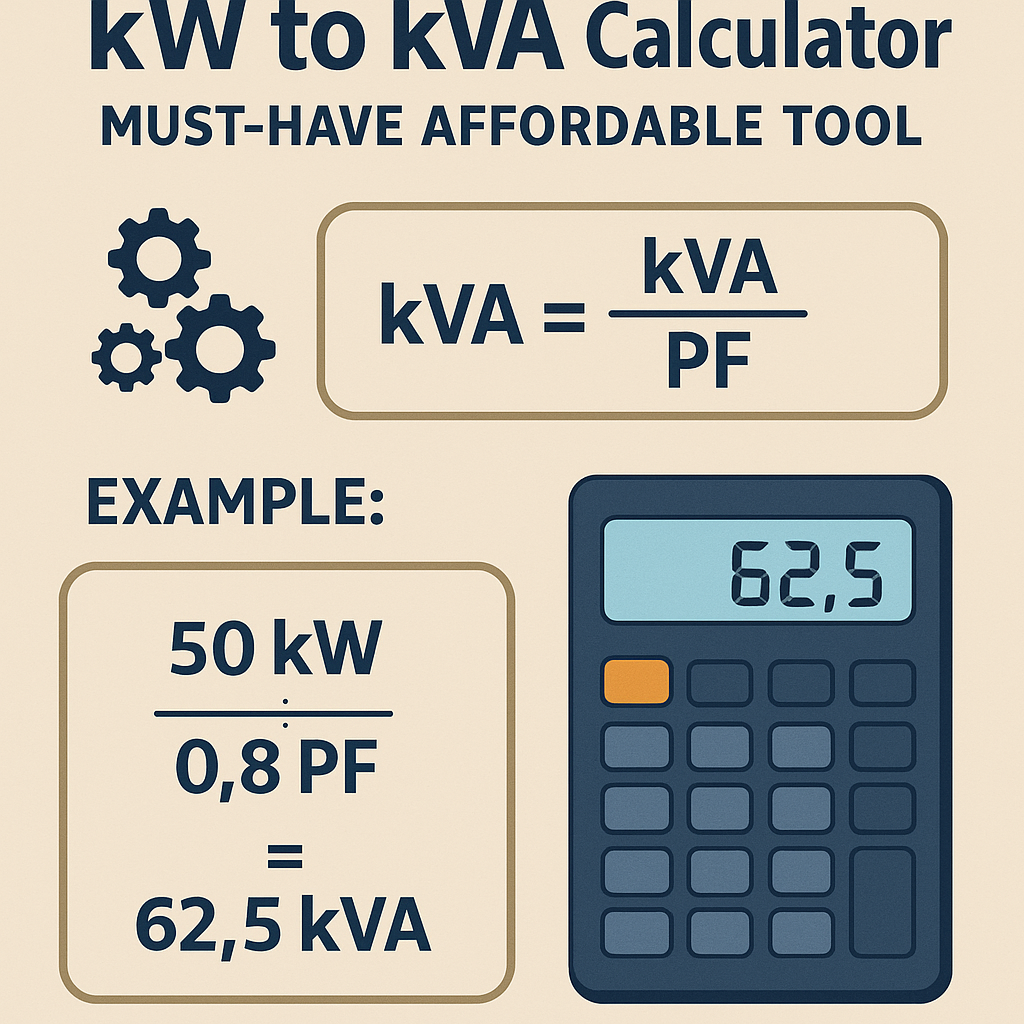
- Apply kVA = kW / PF for individual loads or aggregated totals.
- Aggregate apparent power: sum kVA for simultaneous loads, account for diversity if applicable.
- Add safety margin (10–25%) to determine final equipment rating.
- Check thermal, harmonic, and inrush current requirements; adjust sizing accordingly.
Extensive Conversion Tables — Common Values
The following tables provide precomputed kVA values for typical kW ratings across common power factors used in industrial and commercial engineering. Use these tables for quick lookup in affordable calculators and spreadsheets.
| kW | kVA @ PF 1.00 | kVA @ PF 0.95 | kVA @ PF 0.90 | kVA @ PF 0.85 | kVA @ PF 0.80 | kVA @ PF 0.75 |
|---|---|---|---|---|---|---|
| 1 | 1.00 | 1.05 | 1.11 | 1.18 | 1.25 | 1.33 |
| 5 | 5.00 | 5.26 | 5.56 | 5.88 | 6.25 | 6.67 |
| 10 | 10.00 | 10.53 | 11.11 | 11.76 | 12.50 | 13.33 |
| 20 | 20.00 | 21.05 | 22.22 | 23.53 | 25.00 | 26.67 |
| 50 | 50.00 | 52.63 | 55.56 | 58.82 | 62.50 | 66.67 |
| 100 | 100.00 | 105.26 | 111.11 | 117.65 | 125.00 | 133.33 |
| 200 | 200.00 | 210.53 | 222.22 | 235.29 | 250.00 | 266.67 |
| 500 | 500.00 | 526.32 | 555.56 | 588.24 | 625.00 | 666.67 |
| 1000 | 1000.00 | 1052.63 | 1111.11 | 1176.47 | 1250.00 | 1333.33 |
Another table below shows recommended generator kVA sizes for aggregated building loads using common PF assumptions and safety margins.
| Total kW Load | PF Assumed | Raw kVA | +10% Margin | +20% Margin | Recommended Nominal Generator kVA |
|---|---|---|---|---|---|
| 50 kW | 0.85 | 58.82 | 64.70 | 70.59 | 75–100 kVA |
| 100 kW | 0.90 | 111.11 | 122.22 | 133.33 | 150 kVA |
| 200 kW | 0.90 | 222.22 | 244.44 | 266.67 | 300 kVA |
| 350 kW | 0.85 | 411.76 | 452.94 | 494.11 | 500–600 kVA |
| 500 kW | 0.85 | 588.24 | 647.06 | 705.88 | 750–800 kVA |
Key Engineering Considerations for Affordable Tools
Affordable kW-to-kVA calculators must balance simplicity and fidelity. For professional engineering use they should at least support the following features:
- Per-load PF entry and aggregate PF calculation.
- Three-phase and single-phase modes (with voltage and current based inputs).
- Safety margin options (user-selectable percentages).
- Harmonic derating and non-linear load flags.
- Exportable reports (CSV, PDF) for procurement and compliance documentation.
- Offline operation and lightweight code to run in constrained environments (mobile/web offline).
Why affordability matters for practitioners
- Small engineering firms and contractors often lack budget for enterprise power software.
- Cost-effective calculators reduce procurement delays and enable rapid on-site decisions.
- Open or low-cost tools encourage standardization when compliant with IEC/IEEE guidance.
Real-World Example 1 — Industrial Motor Bank
Scenario: A plant has three identical 150 kW induction motors, each with nameplate PF = 0.88. Motors start with VFDs. Engineer must size a backup generator and choose transformer rating.
Given
- Number of motors: 3
- Each motor active power: 150 kW
- Motor power factor (loaded): PF = 0.88
- System voltage (three-phase): 400 V
- Required safety margin for generator: 20% (due to inrush and VFD harmonics)
Step-by-step calculation
- Aggregate active power: P_total = 3 × 150 kW = 450 kW.
- Compute raw apparent power: kVA_raw = kW_total / PF = 450 / 0.88 = 511.36 kVA.
- Apply safety margin 20%: kVA_design = kVA_raw × 1.20 = 613.63 kVA.
- Select generator/transformer standard nominal size: choose 650 kVA or 700 kVA based on availability and derating tables.
- Line current check (three-phase): I = (kVA_design × 1000) / (√3 × V_LL) = (613.63 × 1000) / (1.732 × 400) ≈ 886 A. Verify switchgear and bus ratings.
Reactive power and correction
kVAR = sqrt( kVA_raw^2 − kW_total^2 ) = sqrt(511.36^2 − 450^2) = sqrt(261,476 − 202,500) ≈ sqrt(58,976) ≈ 242.9 kVAR.
kVA_target = kW_total / 0.95 = 450 / 0.95 = 473.68 kVA.
kVAR_target = sqrt(473.68^2 − 450^2) ≈ sqrt(224,369 − 202,500) ≈ sqrt(21,869) ≈ 148.0 kVAR.
Required capacitor bank ≈ 242.9 − 148.0 = 94.9 kVAR (select nearest commercial size and consider harmonic filtering).
Real-World Example 2 — Data Center UPS and Transformer Sizing
Scenario: A data hall has 350 kW of IT load, with nameplate PF = 0.95. The operator wants to size UPS and utility transformer with 15% growth allowance and consider diversity factor 0.9 for distribution.
Given
- IT load: 350 kW
- PF = 0.95
- Diversity factor: 0.9 (not all loads fully simultaneous)
- Growth allowance: 15%
- Three-phase system voltage: 480 V
Step-by-step calculation
- Apply growth allowance: kW_future = 350 × 1.15 = 402.5 kW.
- Apply diversity: kW_design = kW_future × 0.9 = 402.5 × 0.9 = 362.25 kW.
- Compute kVA without margin: kVA_raw = kW_design / PF = 362.25 / 0.95 = 381.32 kVA.
- Add UPS overhead and power losses: add 10% margin for UPS efficiency and redundancy: kVA_with_UPS = 381.32 × 1.10 = 419.45 kVA.
- Choose standard UPS/transformer rating: 450 kVA to 500 kVA depending on N+1 redundancy strategy.
- Check current: I = (419.45 × 1000) / (1.732 × 480) ≈ 505 A. Ensure switchgear and cables sized accordingly.
Notes on harmonics and non-linear loads
- Data centers have significant non-linear equipment (PSUs, servers). Consider harmonic analysis per IEEE 519 limits and add derating or harmonic filters.
- UPS inverters may require oversizing for nonlinear peaks; consult manufacturer curves for apparent power vs. active power.
Standards, Compliance, and Normative References
Engineers must refer to authoritative standards when sizing power systems. The following references are relevant for kW/kVA conversion, transformer and generator sizing, and power quality.
- IEC 60076 — Power transformers: ratings and loadings. Official: https://www.iec.ch/
- NFPA 70 (NEC) — National Electrical Code for equipment sizing and conductor rules. Official: https://www.nfpa.org/
- IEEE Std 141 (Green Book) — Electric Power Distribution for Industrial Plants: design and applications. IEEE Standards: https://standards.ieee.org/
- IEEE Std 519 — Recommended Practices and Requirements for Harmonic Control in Electrical Power Systems. IEEE Standards: https://standards.ieee.org/
- NEMA MG1 — Motors and Generators guidelines for nameplate ratings and inrush currents. NEMA: https://www.nema.org/
Why cite standards
- Standards provide test conditions, derating factors, ambient corrections, and acceptable performance ranges.
- Compliance ensures safety, insurance acceptance, and interoperability across manufacturers.
Selecting an Affordable kW-to-kVA Calculator — Feature Checklist
The best affordable tools for engineers should provide accurate results, traceability, and easy integration. Use the checklist below to evaluate options:
- Support for single and three-phase calculations with voltage and current inputs.
- Per-load PF and aggregate PF calculation engine.
- User-configurable margins for safety, harmonics, and inrush.
- Exportable calculation reports for project documentation.
- Clear display of intermediate values: raw kVA, kVAR, current, and selection recommendations.
- References to relevant standards or embedded guidance (IEC/IEEE links or citations).
- Low footprint: mobile and offline capability for on-site use.
Verification, Testing, and Practical Deployment Tips
- Always validate calculator outputs against measured values: use clamp meters and power quality analyzers to measure kW, kVAR, and PF in-situ.
- Perform a load study across operating cycles to capture diversity and transient conditions.
- Document assumptions: PF assumptions, simultaneity, safety margins, and environmental derating factors.
- When in doubt, oversize to the nearest standard equipment rating and document rationale for procurement teams.
- Reassess after commissioning with actual measured data and adjust capacitor banks or transformer taps as necessary.
SEO and Documentation Recommendations for Engineers
When publishing tools or calculators online, include the following for discoverability and professional use:
- Clear keyword targeting: "kW to kVA calculator", "kw to kva converter", "kVA sizing tool", "affordable power calculator".
- Metadata describing supported standards (IEC, IEEE, NFPA) and common applications (motors, UPS, generators).
- Step-by-step worked examples (as provided above) to show transparency and trustworthiness.
- Downloadable tables and exportable calculation logs for audit trails.
Advanced Considerations for Accurate Apparent Power Estimation
- Harmonic distortion increases apparent current without adding useful kW; use harmonic impedance models and IEEE 519 compliance checks.
- Inrush currents for motors and transformers can exceed steady-state values by 5–10×; ensure short-time withstand ratings on protection devices.
- Temperature and altitude derating for generators per manufacturer and IEC/ISO standards.
- Non‑sinusoidal waveforms: PF may be split between displacement PF and distortion PF; reference IEEE 1459 for definitions.
Maintenance and Periodic Recalculation
System loads change; periodic recalculation ensures sustained reliability and cost efficiency.
- Schedule load audits annually or after major equipment changes.
- Reconcile measured PF and kW with design assumptions.
- Update capacitor banks and replace undersized transformers or generators when required by updated load profiles.
Reference Tools and External Resources
- IEC Standards Portal: https://www.iec.ch/ — browse IEC 60076 and installation standards.
- IEEE Xplore / Standards: https://standards.ieee.org/ — consult IEEE 141, IEEE 519.
- NFPA Codes and Standards: https://www.nfpa.org/ — NEC and safety codes.
- NEMA Resources: https://www.nema.org/ — motor and generator guidance.
- US Department of Energy (DOE) — guidance on power factor and energy efficiency: https://www.energy.gov/
Final Recommendations for Engineers Choosing an Affordable Calculator
- Prioritize calculators that surface intermediate values, not just final kVA, to allow engineering review.
- Ensure the tool references standards and allows entry of site-specific derating (altitude, temperature, harmonics).
- Implement a simple verification step: compare the calculator's predicted currents and kVA against measured values during commissioning.
- Document all assumptions in a traceable report for procurement and compliance.
Quick checklist for on-site use
- List all loads (kW) and measured/nameplate PF.
- Choose aggregated PF if individual PFs unknown (conservative: 0.85–0.90).
- Calculate kVA = kW / PF and sum for simultaneous loads.
- Add margins for harmonics/inrush (10–25%).
- Select standard equipment rating and confirm thermal/short‑time current capability.
- Validate with measurements and adjust as needed.
References
- IEC 60076 — Power transformers. IEC. https://www.iec.ch/
- NFPA 70 — National Electrical Code. NFPA. https://www.nfpa.org/
- IEEE Std 141 — IEEE Recommended Practice for Electric Power Distribution for Industrial Plants. IEEE. https://standards.ieee.org/
- IEEE Std 519 — Harmonic Control in Electrical Power Systems. IEEE. https://standards.ieee.org/
- NEMA MG1 — Motors and Generators. NEMA. https://www.nema.org/
- U.S. Department of Energy — Power factor and energy efficiency guidance. https://www.energy.gov/
Using an affordable, standards-aware kW-to-kVA calculator increases accuracy in equipment selection, reduces overspecification costs, and improves operational reliability. Follow the procedures and examples above to implement reliable conversions, document assumptions, and comply with relevant standards for safe, economical power system design.