This article provides advanced three-phase voltage drop calculation methods with precision, clarity, and practical guidance.
Engineers require accurate calculators, normative compliance, and interpretative examples for reliable electrical design decisions worldwide.
Three-Phase Voltage Drop Calculator — Technical
Fundamentals of Three-Phase Voltage Drop
Voltage drop in three-phase systems is the result of the impedance of conductors carrying current. For a balanced three-phase load the line-to-line voltage drop magnitude is dominated by the product of current, conductor impedance per unit length, electrical length, and the load phase angle.Key influences on voltage drop:- Conductor material (copper, aluminium) and cross-sectional area (mm²)
- Conductor AC resistance and reactance per unit length (R, X in ohm/km)
- Load current magnitude I (A) and power factor φ (cosφ)
- Physical length of the run L (km) and grouping/corridor installation effects
- Operating temperature and temperature coefficient of resistance
Balanced three-phase formula (line-to-line)
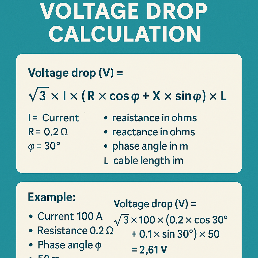
ΔV = √3 × I × (R cosφ + X sinφ) × L
- ΔV: Line-to-line voltage drop (V)
- I: Line current per phase (A)
- R: Conductor resistance per unit length (ohm/km) at reference temperature
- X: Conductor reactance per unit length (ohm/km)
- φ: Load phase angle (power factor angle), where cosφ is power factor
- L: One-way conductor length (km)
ΔV_phase = I × (R cosφ + X sinφ) × L
%ΔV = (ΔV / V_line) × 100
Temperature correction of resistance
Conductor resistance varies with temperature. Use:R_T = R_20 × [1 + α × (T - 20)]
- R_T: resistance at operating temperature T (°C)
- R_20: resistance at 20 °C (ohm/km)
- α: temperature coefficient (≈0.00393 /°C for copper, ≈0.00403 /°C for aluminium)
- T: conductor operating temperature (°C)
R_75 = 0.3448 × [1 + 0.00393 × (75 - 20)] = 0.3448 × [1 + 0.216] ≈ 0.419
Typical conductor parameters and reference tables
Below are extensive typical reference tables used in practical voltage drop calculators. Values are representative at 20 °C for resistance and typical reactance for 50 Hz installations; verify with local code or manufacturer data for high accuracy.| Cu conductor (mm²) | R @20°C (ohm/km) | Typical X @50Hz (ohm/km) | R @75°C (ohm/km) (approx) |
|---|---|---|---|
| 1.5 | 11.494 | 0.080 | 13.97 |
| 2.5 | 6.896 | 0.080 | 8.38 |
| 4 | 4.310 | 0.080 | 5.24 |
| 6 | 2.873 | 0.080 | 3.49 |
| 10 | 1.724 | 0.078 | 2.09 |
| 16 | 1.0776 | 0.078 | 1.31 |
| 25 | 0.6896 | 0.076 | 0.84 |
| 35 | 0.4926 | 0.075 | 0.60 |
| 50 | 0.3448 | 0.073 | 0.42 |
| 70 | 0.2463 | 0.071 | 0.30 |
| 95 | 0.1815 | 0.070 | 0.22 |
| 120 | 0.1437 | 0.069 | 0.18 |
| 150 | 0.1149 | 0.068 | 0.14 |
| 185 | 0.0932 | 0.067 | 0.11 |
| 240 | 0.0718 | 0.066 | 0.087 |
| Al conductor (mm²) | R @20°C (ohm/km) | Typical X @50Hz (ohm/km) | R @75°C (ohm/km) (approx) |
|---|---|---|---|
| 16 | 1.7665 | 0.080 | 2.31 |
| 25 | 1.1306 | 0.078 | 1.48 |
| 35 | 0.8090 | 0.077 | 1.06 |
| 50 | 0.5653 | 0.075 | 0.74 |
| 70 | 0.4038 | 0.073 | 0.53 |
| 95 | 0.2975 | 0.071 | 0.39 |
| 120 | 0.2355 | 0.070 | 0.30 |
| 150 | 0.1884 | 0.069 | 0.24 |
| 185 | 0.1527 | 0.068 | 0.20 |
| 240 | 0.1178 | 0.067 | 0.15 |
- R values are computed from resistivity at 20 °C: copper ≈ 0.017241 ohm·mm²/m, aluminium ≈ 0.028264 ohm·mm²/m.
- X values are typical for common LV installations and depend on conductor arrangement and spacing; bundling and conduits increase X.
- Use manufacturer or standards data (IEC 60287) for final design.
Calculator design considerations and UX features
A high-quality three-phase voltage drop calculator must support:- Material selection: copper/aluminium with selectable temperature coefficients.
- Conductor size selection with R and X tables and ability to import manufacturer data.
- Length units (m, km), current inputs either as I (A) or as power P (kW) with selectable power factor.
- System voltage selection (line-to-line), single-phase/three-phase mode, and harmonic load influence.
- Temperature correction and grouping/derating factors for bundled cables.
- Outputs: absolute voltage drop (V), percentage drop, and recommended upsizing suggestions to meet code limits.
- Show intermediate steps and formulas for traceability (benefits engineers and auditors).
- Allow export of calculation report including normative references and assumptions.
- Include warnings when results exceed common limits or when conductor thermal ratings may be exceeded.
Regulatory and normative limits
Common recommended maximum voltage drops:| Regulatory source | Typical recommended limit | Scope |
|---|---|---|
| IEC/BS 7671 (guidance) | Typically 3% branch, 5% total | Low-voltage installations; guidance may vary by country |
| NEC (NFPA 70) recommendation | 3% for branch circuits, 5% for feeder+branch | Recommended practice in the USA (not mandatory) |
| IEEE/other engineering practice | 1%–5% depending on sensitivity of equipment | Transformer and motor sensitive applications often tighter |
Worked examples with complete development
Below are two full examples demonstrating step-by-step calculations suitable for inclusion in a calculator result page.Example 1 — Motor feeder, 50 kW three-phase motor at 400 V (Cu conductor)
Scenario:- Load: 50 kW three-phase motor
- System voltage: 400 V (line-to-line)
- Power factor: cosφ = 0.85 (lagging)
- Feeder length: 100 m (one-way)
- Conductor: copper, 50 mm²
- Ambient conditions: use R_20 values, assume moderate conductor temperature (no further correction in base case)
I = P / (√3 × V_line × cosφ)
- P = 50,000 W
- √3 ≈ 1.732
- V_line = 400 V
- cosφ = 0.85
I = 50000 / (1.732 × 400 × 0.85) = 50000 / 588.88 ≈ 84.9 A
- R @20°C for Cu 50 mm² = 0.3448 ohm/km (from table)
- X typical = 0.073 ohm/km
- L = 100 m = 0.1 km
- sinφ = √(1 − cos²φ) = √(1 − 0.7225) = √0.2775 ≈ 0.5268
(R cosφ + X sinφ) = 0.3448 × 0.85 + 0.073 × 0.5268 = 0.2931 + 0.0385 ≈ 0.3316 (ohm/km)
Step 4 — Apply three-phase formula:ΔV = √3 × I × (R cosφ + X sinφ) × L
ΔV = 1.732 × 84.9 × 0.3316 × 0.1 ≈ 1.732 × 84.9 × 0.03316 ≈ 1.732 × 2.815 ≈ 4.876 V
%ΔV = (4.876 / 400) × 100 ≈ 1.22%
- Line current ≈ 84.9 A
- Voltage drop ≈ 4.9 V (1.22%) — well within typical 3% branch limit
Example 2 — Long distribution feeder, aluminium conductors
Scenario:- Feeder: 300 A balanced three-phase load at 400 V
- Power factor: cosφ = 0.95
- Length: 200 m (0.2 km)
- Conductor: aluminium, 150 mm²
I = 300 A (stated)
- R @20°C for Al 150 mm² = 0.1884 ohm/km
- X typical = 0.069 ohm/km
- L = 0.2 km
- sinφ = √(1 − 0.95²) = √(1 − 0.9025) = √0.0975 ≈ 0.31225
(R cosφ + X sinφ) = 0.1884 × 0.95 + 0.069 × 0.31225 = 0.1790 + 0.0215 = 0.2005 (ohm/km)
Step 4 — Apply three-phase formula:ΔV = √3 × I × (R cosφ + X sinφ) × L
ΔV = 1.732 × 300 × 0.2005 × 0.2 = 1.732 × 300 × 0.04010 ≈ 1.732 × 12.03 ≈ 20.84 V
Step 5 — Percentage:%ΔV = (20.84 / 400) × 100 ≈ 5.21%
- Voltage drop ≈ 20.8 V (≈5.21%) — exceeds common 5% total limit
- Mitigation: increase conductor size (e.g., to Al 185 mm²) or reduce length or use copper conductors
(R cosφ + X sinφ) ≈ 0.1527×0.95 + 0.068×0.31225 = 0.1450 + 0.0212 = 0.1662
ΔV_new = 1.732 × 300 × 0.1662 × 0.2 ≈ 17.27 V => 4.32%
Advanced topics and corrections
Grouping and mutual coupling
When multiple circuits are grouped in a conduit, DC resistance stays same but AC resistance and reactance vary due to proximity and skin effect. Corrective factors:- Proximity increase effective X and sometimes R; consult IEC 60287 or manufacturer data.
- Apply grouping correction factors (k_group) to R and X or use tabulated impedance for installed configuration.
Harmonics
Harmonic currents increase RMS current and can increase losses and heating; use:- Equivalent RMS current I_eq = √(I1² + I3² + I5² + ...)
- Calculate voltage drop using I_eq and consider additional skin/proximity effects increasing R and X at harmonic frequencies.
Transformers and unbalanced loads
For systems with significant unbalance or delta-star transformer configurations, calculate per-phase drops individually using phase currents and corresponding conductor impedances. For unbalanced systems the simple balanced formula can underestimate worst-phase drop.Implementation checklist for an 'Epic Best' calculator
To market a leading three-phase voltage drop calculator emphasize:- Precision: allow user override of R/X inputs and include temperature adjustments.
- Transparency: show step-by-step math and intermediate values.
- Normative guidance: display recommended maximums per IEC/NEC and allow selection of target limits.
- Optimization: provide “what-if” upsizing suggestions and auto-search the minimum conductor size meeting limits.
- Exportable compliance report: include assumptions, normative references, and traceable inputs/outputs.
Normative references and authoritative resources
Key standards and references (authoritative):- IEC 60287 — Electric cables — Calculation of the continuous current rating (ampacity) — impedance and losses reference (purchase required); see IEC (https://www.iec.ch)
- IEC 60364 series / BS 7671 — Requirements for electrical installations (guidance on voltage drop and wiring rules); see national adoption documentation
- NFPA 70 (NEC) — Article on voltage drop recommendations (United States) (https://www.nfpa.org)
- Engineering ToolBox — Resistivity, conductor resistance, and X/R typical values (technical reference) (https://www.engineeringtoolbox.com)
- Electric Power Research Institute (EPRI) or IEEE papers on power system voltage regulation and conductor modeling — consult IEEE Xplore (https://ieeexplore.ieee.org)
Practical tips and validation
Practical steps to validate calculator outputs:- Cross-check R and X values with manufacturer cable data sheets for the exact construction and installation method.
- Perform a sensitivity analysis by varying power factor, length, and temperature to identify worst-case drop.
- If possible, measure voltage at the remote load in a commissioning test and compare to calculated values (accounting for instrument accuracy).
- Include safety margins: when critical equipment is involved, design for a lower percentage drop than the maximum permitted.
Summary of essential formulas and quick reference
Key formulas to include as visible help in any calculator interface:- Line current from three-phase power:I = P / (√3 × V_line × cosφ)
- Three-phase line-to-line voltage drop:ΔV = √3 × I × (R cosφ + X sinφ) × L
- Phase (line-to-neutral) voltage drop:ΔV_phase = I × (R cosφ + X sinφ) × L
- Percentage voltage drop:%ΔV = (ΔV / V_line) × 100
- Temperature correction:R_T = R_20 × [1 + α × (T - 20)]
References for further reading
Suggested authoritative reading for advanced design:- IEC 60287 series — cable impedance and current rating calculations (official standard).
- BS 7671 (IET Wiring Regulations) — guidance on voltage drop criteria (UK).
- NFPA 70 (NEC) Handbook articles on voltage drop recommendations (USA).
- Engineering Toolbox — practical tables and calculators for conductivity and resistivity: https://www.engineeringtoolbox.com
- IEEE Xplore — technical papers on cable modelling, harmonics and voltage regulation: https://ieeexplore.ieee.org