HP = (V × I × PF × η) ÷ 746 (1Φ) · HP = (V × I × PF × η × 1.732) ÷ 746 (3Φ) · 1 HP = 746 W📊 Quick Reference Table (Amps → HP at 460 V, 3Φ)
| Amps | HP (η=90%) | Typical Use |
|---|---|---|
| 1 A | 0.82 HP | Small fan |
| 5 A | 4.09 HP | Workshop motor |
| 10 A | 8.2 HP | Air compressor |
| 15 A | 12.26 HP | Conveyor belt |
| 20 A | 16.34 HP | Industrial pump |
| 30 A | 24.51 HP | Large blower |
| 50 A | 40.85 HP | Chiller unit |
| 100 A | 81.70 HP | Crusher motor |
| 400 A | 326.81 HP | Plant MCC feeder |
❓ Calculator FAQ
Why do I need voltage? Amps alone don’t define power. You need volts, power factor, and efficiency to get an accurate HP value.
🔄 Need the reverse calculation? If you need to convert from HP to AMP (the opposite direction of this page), use our dedicated HP to AMP calculator with full conversion tables, step-by-step examples, and engineering formulas.
What power factor should I use? Use 0.85 for typical induction motors. Check the motor nameplate for exact data.
Input vs output HP? This calculator gives the mechanical output HP at the shaft, which accounts for efficiency losses.
When you read 30 amps on a motor feeder and need the mechanical horsepower at the shaft, the conversion is not a simple ratio — you need voltage, power factor, efficiency, and phase count. This amps to HP calculator handles all of that for you in one step. Below you’ll find the formulas used in the field, conversion tables with standard motor values, and fully worked examples that mirror scenarios you’ll face on a job site or in a design review.
Amps to HP Conversion Table — Standard Motor Ratings
This table uses the most common industrial conditions: 460 V, three-phase, power factor 0.85, and motor efficiency 90%. These are the values you’ll see on the majority of NEMA-rated induction motors in North American plants. If your voltage or efficiency differs, use the calculator above for an exact result.
| Current (A) | HP (output) | kW equivalent | Typical application |
|---|---|---|---|
| 1 A | 0.82 HP | 0.61 kW | Small exhaust fan, instrument cooling |
| 3 A | 2.45 HP | 1.83 kW | Sump pump, small mixer |
| 5 A | 4.09 HP | 3.05 kW | Workshop drill press, ventilation fan |
| 10 A | 8.17 HP | 6.09 kW | Air compressor, process pump |
| 12 A | 9.80 HP | 7.31 kW | Centrifugal blower |
| 15 A | 12.26 HP | 9.14 kW | Conveyor belt drive |
| 20 A | 16.34 HP | 12.19 kW | Hydraulic unit pump |
| 30 A | 24.51 HP | 18.28 kW | Large centrifugal fan, chiller compressor |
| 40 A | 32.68 HP | 24.37 kW | Crusher motor, large agitator |
| 50 A | 40.85 HP | 30.46 kW | Chiller unit, cooling tower fan |
| 75 A | 61.28 HP | 45.69 kW | Large HVAC blower, process pump |
| 100 A | 81.70 HP | 60.93 kW | Rock crusher, large compressor |
| 200 A | 163.41 HP | 121.85 kW | Mill drive, heavy extruder |
| 400 A | 326.81 HP | 243.71 kW | MCC main feeder, cement kiln drive |
Verification: every value in the table follows HP = (460 × A × 0.85 × 0.90 × 1.732) ÷ 746. For example, 10 A → (460 × 10 × 0.85 × 0.90 × 1.732) ÷ 746 = 6,094.91 ÷ 746 = 8.17 HP.
Step-by-Step Formulas — Amps to HP Conversion
There are two formulas you need depending on the motor type. Both come from the fundamental relationship that 1 mechanical horsepower equals 746 watts, combined with the power formula for AC circuits.
HP = (V × I × PF × η) ÷ 746
HP = (V × I × PF × η × 1.732) ÷ 746
Where V is the line voltage in volts, I is the line current in amperes, PF is the power factor (dimensionless, between 0 and 1), η (eta) is the motor efficiency (also between 0 and 1), and 746 is the conversion constant from watts to horsepower. The factor 1.732 (which is √3) accounts for the phase relationship in three-phase systems.
Why you can’t skip PF and efficiency: amps measure the current the motor draws from the line, but not all of that current produces useful mechanical work. The power factor tells you how much of the apparent power is real power, and efficiency tells you how much of the electrical input becomes shaft output. Omitting either one gives you a number that doesn’t match the motor nameplate.
These formulas align with the definitions published by IEEE in standard 112 for induction motor testing and by NEMA in MG 1 for motor ratings. If you’re working with IEC motors, the approach is identical — only the efficiency class labels (IE1 through IE5) differ, as defined by IEC 60034-30-1.
AC Single-Phase vs Three-Phase — Key Differences
The choice of phase directly affects how amps translate to horsepower. Here’s a side-by-side comparison so you know which formula to apply and what to expect in practice.
| Parameter | Single-phase (1Φ) | Three-phase (3Φ) |
|---|---|---|
| Formula factor | V × I × PF × η | V × I × PF × η × 1.732 |
| Common voltages | 120 V, 230 V, 240 V | 208 V, 460 V, 480 V, 600 V |
| Typical HP range | Up to 10 HP | 1 HP to 500+ HP |
| Line current for 10 HP at 230 V | ~43 A | ~25 A |
| Where you’ll find it | Residential, small shops | Industrial, commercial, plants |
| Power factor range | 0.80–0.95 | 0.80–0.95 |
| Efficiency range | 0.70–0.90 | 0.85–0.96 (NEMA Premium) |
| Wire count | 2 conductors + ground | 3 conductors + ground |
The key takeaway: a three-phase motor draws significantly less current for the same horsepower than a single-phase motor, because the three-phase system delivers power more efficiently through the √3 factor. That’s why industrial facilities overwhelmingly use three-phase motors for anything above a few horsepower.
HP to Amps — Inverse Conversion
Sometimes you have the motor HP rating from the nameplate and need to know how many amps it draws — for example, when sizing conductors, breakers, or starters. The inverse formula rearranges the same relationship.
Three-phase: I = (HP × 746) ÷ (V × PF × η × 1.732)
| HP | Amps at 460 V, 3Φ | Amps at 230 V, 1Φ |
|---|---|---|
| 1 HP | 1.22 A | 4.24 A |
| 3 HP | 3.67 A | 12.72 A |
| 5 HP | 6.12 A | 21.20 A |
| 10 HP | 12.24 A | 42.40 A |
| 15 HP | 18.36 A | — |
| 25 HP | 30.60 A | — |
| 50 HP | 61.20 A | — |
| 100 HP | 122.39 A | — |
For the full inverse conversion with an interactive tool, check out our Amp to kW Calculator and the Amps to Watts Calculator — both handle related electrical conversions you’ll need when sizing circuits.
6 Solved Examples — Real Motor Scenarios
Example 1 — Workshop Air Compressor (Single-Phase)
Data: 12 A, 230 V, single-phase, PF = 0.90, η = 0.85
Formula: HP = (230 × 12 × 0.90 × 0.85) ÷ 746
Calculation: HP = (2,110.68) ÷ 746 = 2.83 HP
A typical 3 HP rated compressor running in a woodworking shop. The calculated 2.83 HP output confirms the motor is operating near its rated load — healthy for longevity.
Example 2 — Industrial Pump (Three-Phase, 460 V)
Data: 30 A, 460 V, three-phase, PF = 0.85, η = 0.92
Formula: HP = (460 × 30 × 0.85 × 0.92 × 1.732) ÷ 746
Calculation: HP = (18,691.60) ÷ 746 = 25.06 HP
This matches a 25 HP NEMA-rated centrifugal pump motor. At 30 A the motor is at full load — if you measure consistently above this, check the impeller for wear or a partially clogged strainer.
Example 3 — Residential Pool Pump (Single-Phase, 120 V)
Data: 10 A, 120 V, single-phase, PF = 0.80, η = 0.80
Formula: HP = (120 × 10 × 0.80 × 0.80) ÷ 746
Calculation: HP = (768) ÷ 746 = 1.03 HP
A 1 HP pool pump on a standard 120 V outlet. Drawing 10 A is expected; the breaker on this circuit should be 15 A or 20 A per NEC 430.
Example 4 — Conveyor Belt Motor (Three-Phase, 208 V)
Data: 15 A, 208 V, three-phase, PF = 0.85, η = 0.88
Formula: HP = (208 × 15 × 0.85 × 0.88 × 1.732) ÷ 746
Calculation: HP = (4,043.12) ÷ 746 = 5.42 HP
A 5 HP conveyor motor in a warehouse distribution center running at 208 V (common in commercial buildings). The current draw slightly above nameplate is normal under a heavy load of packages.
Example 5 — Large Chiller Compressor (Three-Phase, 480 V)
Data: 400 A, 480 V, three-phase, PF = 0.88, η = 0.95
Formula: HP = (480 × 400 × 0.88 × 0.95 × 1.732) ÷ 746
Calculation: HP = (278,014.94) ÷ 746 = 372.67 HP
This is a 400 HP-class centrifugal chiller compressor in a commercial high-rise. At 95% efficiency (premium motor), the 372.67 HP output means it’s running at about 93% load — perfectly healthy for continuous duty.
Example 6 — Inverse: How Many Amps Does a 50 HP Motor Draw?
Data: 50 HP, 460 V, three-phase, PF = 0.85, η = 0.92
Formula: I = (50 × 746) ÷ (460 × 0.85 × 0.92 × 1.732)
Calculation: I = (37,300) ÷ (623.05) = 59.87 A
A 50 HP motor at full load draws about 60 A. Per NEC Table 430.250, the full-load current for a 50 HP, 460 V motor is 65 A — the slight difference comes from the table using conservative values for conductor sizing.
Understanding Motor Nameplate Data — Input vs Output Power
One of the most common mistakes when converting amps to HP is confusing input power with output power. The nameplate on every motor tells you the rated output horsepower — that’s the mechanical power delivered at the shaft. The current you read with a clamp meter is the input side.
Input power (electrical): P_in = V × I × PF (single-phase) or V × I × PF × √3 (three-phase). This is what the motor draws from the supply in watts.
Output power (mechanical): P_out = P_in × η. This is the actual shaft horsepower the motor delivers. The difference between input and output is heat — winding resistance, core losses, friction, and windage.
For a NEMA Premium motor rated at 50 HP and 93% efficiency, the input power is 50 ÷ 0.93 = 53.76 HP worth of electrical energy. That extra 3.76 HP becomes heat inside the motor frame. This is why motor cooling matters — and why you should never block ventilation openings on a TEFC motor.
When you use the amps to HP calculator above, it automatically accounts for efficiency to give you the mechanical output. If you need the electrical input instead (for sizing cable or circuit breakers), set efficiency to 100% — but for most engineering purposes, the output HP is what you want.
For a deeper look at motor efficiency calculations and how to read nameplate data correctly, check our Electric Motor Efficiency Calculator.
Quick Equivalences — Amps to HP
These are the most searched conversions. Each one uses 460 V, three-phase, PF = 0.85, and η = 0.90 unless stated otherwise. For single-phase values, the voltage is 230 V.
1 Amp to HP
0.82 HP (3Φ, 460 V)
At single-phase 230 V: 0.24 HP. A single amp alone produces very little mechanical output.
10 Amps to HP
8.17 HP (3Φ, 460 V)
Typical current draw for a 7.5 HP to 10 HP air compressor or process pump.
12 Amps to HP
9.80 HP (3Φ, 460 V)
A 10 HP motor at near-full load. This is right at the upper operating limit for the rating.
15 Amps to HP
12.26 HP (3Φ, 460 V)
Matches a standard 15 HP motor operating at about 80% load — efficient and within the thermal design range.
30 Amps to HP
24.51 HP (3Φ, 460 V)
A 25 HP motor near full load. Commonly found in HVAC blower units and building ventilation systems.
400 Amps to HP
326.81 HP (3Φ, 460 V)
Heavy industrial territory — cement kiln drives, large mining crushers, MCC main feeders in manufacturing plants.
Ampere to HP (general rule)
1 A ≈ 0.82 HP (3Φ, 460 V)
This ratio changes with voltage. At 230 V single-phase: 1 A ≈ 0.24 HP. Always specify the voltage.
Amp to HP at 120 V (single-phase)
1 A ≈ 0.12 HP (1Φ, 120 V)
At 120 V, the HP-per-amp ratio is very low. A 15 A household circuit can power roughly 1.8 HP maximum.
Frequently Asked Questions — Amps to HP
How many HP is 1 amp?
At 460 V three-phase with PF 0.85 and 90% efficiency, 1 amp equals 0.82 HP. The formula is HP = (460 × 1 × 0.85 × 0.90 × 1.732) ÷ 746 = 0.82. This value changes dramatically with voltage — at 120 V single-phase it drops to just 0.12 HP.
How do you convert amps to horsepower?
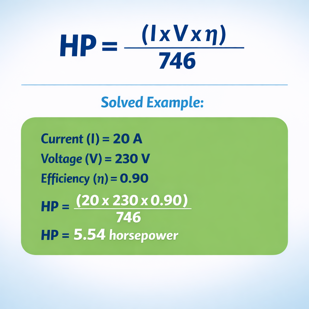
Use the formula HP = (V × I × PF × η × √3) ÷ 746 for three-phase, or HP = (V × I × PF × η) ÷ 746 for single-phase. You need four values: voltage, current in amps, power factor, and motor efficiency. Example: 20 A at 460 V, 3Φ, PF 0.85, η 0.90 → HP = (460 × 20 × 0.85 × 0.90 × 1.732) ÷ 746 = 16.34 HP.
Can I convert amps to HP without knowing the voltage?
No. Amps alone do not define power. You must know the voltage, power factor, and efficiency. Two motors drawing the same 10 A could produce very different HP: 10 A at 120 V single-phase gives 1.23 HP, while 10 A at 460 V three-phase gives 8.17 HP.
What is the power factor and why does it matter?
Power factor is the ratio of real power (watts) to apparent power (volt-amps). For motors, it typically ranges from 0.75 to 0.95. A motor with a low power factor draws more current for the same output, which increases cable size and energy costs. Most industrial induction motors run at 0.80–0.90 PF at full load.
What efficiency should I use for my motor?
Check the motor nameplate first. If unavailable: use 90% for standard motors above 10 HP, 85% for older or smaller motors (under 10 HP), and 93–95% for NEMA Premium or IE3/IE4 rated motors. These percentages come from NEMA MG 1 Table 12-12.
How many amps does a 1 HP motor draw?
At 460 V three-phase, a 1 HP motor draws about 1.22 A (with PF 0.85, η 0.90). At 230 V single-phase, it draws about 4.24 A. Use the inverse formula I = (HP × 746) ÷ (V × PF × η × √3 for 3Φ).
Is the HP from this calculator input or output power?
Output power — mechanical horsepower at the shaft. The efficiency factor in the formula accounts for the losses between electrical input and mechanical output. If you want the electrical input in HP, set efficiency to 100%.
Why doesn’t my clamp meter reading match the motor nameplate amps?
The nameplate shows full-load amps (FLA) at rated voltage and HP. If the motor runs at partial load, amps will be lower. If voltage is low, amps increase. Unbalanced phases on three-phase systems also cause individual phase currents to differ. A deviation of 5–10% is normal in field conditions.
What’s the difference between FLA and actual measured amps?
FLA (full-load amperes) is the nameplate current at rated output and voltage. Measured amps reflect real operating conditions — load level, actual voltage, ambient temperature, and mechanical condition. If measured amps consistently exceed FLA by more than 10%, investigate for overloading, low voltage, or mechanical binding.
Can I use this calculator for DC motors?
Not directly. DC motors don’t have a power factor. For DC: HP = (V × I × η) ÷ 746. Remove the PF and √3 terms. Set PF to 1.00 and phase to single-phase in the calculator as a workaround — this gives a close approximation if you input the correct DC voltage and efficiency.
How does voltage affect the amps-to-HP ratio?
Higher voltage means fewer amps for the same HP. A 10 HP motor at 460 V draws about 12.24 A, but the same motor at 230 V draws 24.48 A — exactly double. This is why industrial plants use 460 V or 480 V: smaller conductors, lower losses, and cheaper installations.
Where does the 746 constant come from?
James Watt defined 1 HP as 550 ft·lbf per second in the 18th century based on the work output of draft horses. Converting to SI units: 550 ft·lbf/s × 1.35582 W/(ft·lbf/s) = 745.7 W, rounded to 746 W. This is a fixed conversion factor used worldwide in electrical engineering.
Related Conversions
These calculators on our site handle related electrical and power conversions you’ll use alongside amps to HP:
- Amp to kW Calculator — convert amperes to kilowatts with formulas and tables
- Amps to Watts Calculator — convert amps to watts for any voltage and phase
- Amperes to VA Calculator — for sizing transformers and UPS systems
- Amperes to Resistance (Ohm’s Law) Calculator — current to resistance conversion
- Electric Motor Efficiency Calculator — calculate motor efficiency from nameplate data
- AWG to mm² Equivalences — wire sizing reference for motor feeders
- Balanced and Unbalanced Load Calculation — three-phase load distribution