This article explains PF-aware UPS sizing for motors, lighting, and instant kVA to kW conversion.
Focus on calculations, formulas, standards, practical examples, and normative references for precise UPS selection applications.
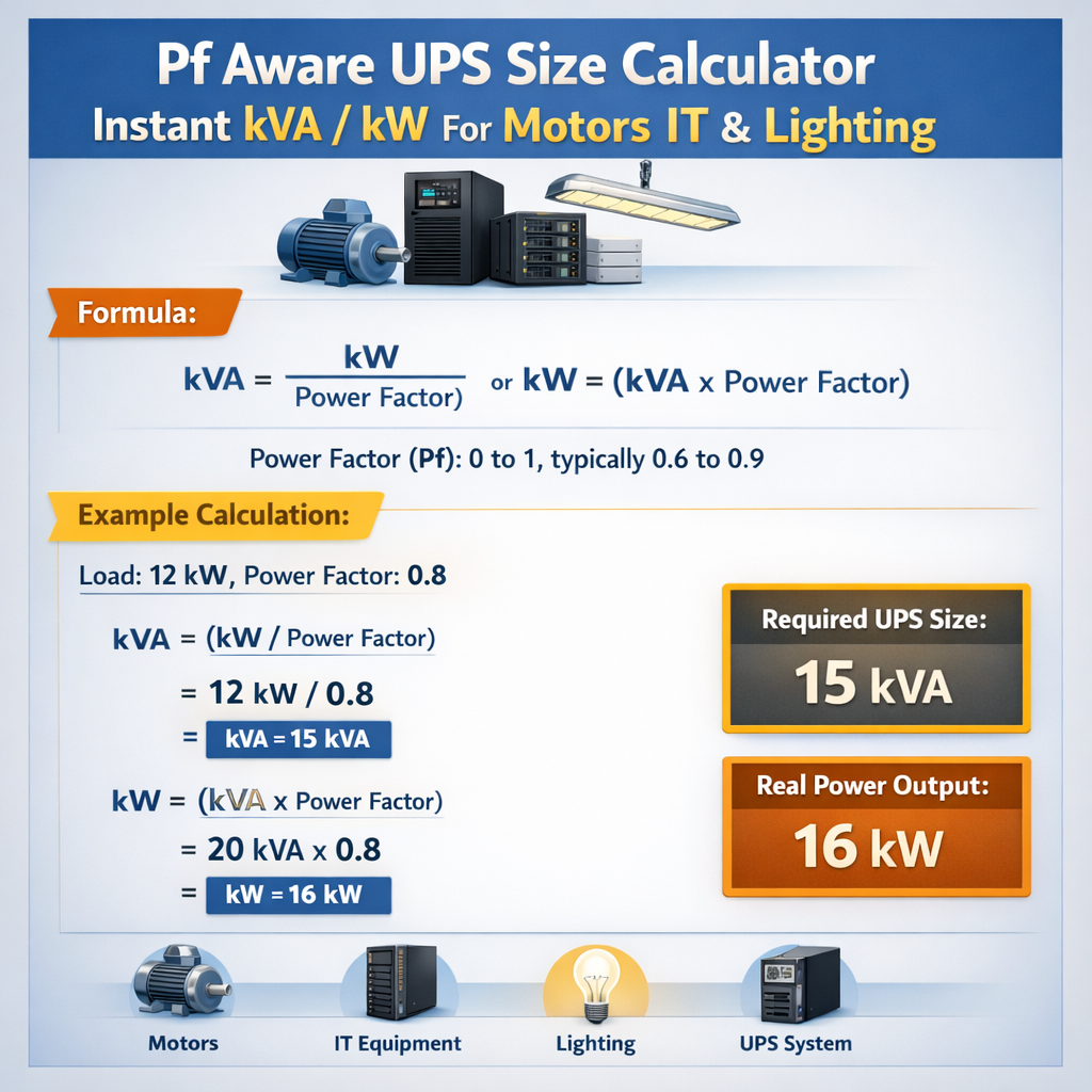
PF-aware UPS Instant Sizing — Recommended kVA & kW for Motors, IT, Lighting
Fundamentals of power factor and UPS ratings
Power factor (PF) links real power (kW) to apparent power (kVA) and determines UPS sizing. PF is the cosine of the phase angle (φ) between voltage and current in linear systems. For non-linear loads, PF includes distortion from harmonics; true PF = displacement PF × distortion factor.
UPS manufacturers rate units in kVA and specify maximum deliverable kW at a given PF (for example, 0.9 or 1.0). Selecting a UPS without PF awareness yields undersized systems or unnecessary oversizing.
Key electrical relationships and definitions
Use these core relationships when sizing UPS for motors, lighting and mixed loads.
- Real power (P) in kilowatts (kW) — the useful power consumed by equipment.
- Apparent power (S) in kilovolt-amperes (kVA) — the product of RMS voltage and current. S = V × I (single-phase) or S = √3 × VLL × I (three-phase).
- Reactive power (Q) in kilovolt-amp reactive (kVAr) — the power exchanged but not consumed, Q = S × sin(φ).
- Power factor (PF) — PF = P / S = cos(φ) for sinusoidal waveforms; for distorted waveforms PF includes distortion.
Essential formulas for PF-aware UPS sizing
Presenting formulas using standard text notation and describing variables with typical values.
1) Convert kW to kVA (single value, PF known):
Where:
- P (kW) = real load power, typical values: lighting 0.8–5 kW circuits, motors 1–500 kW.
- PF = power factor (unitless), typical: LED lighting 0.6–0.95; induction motors 0.8–0.9; modern UPS rated PF 0.9–1.0.
2) Three-phase current from kW:
Where:
- VLL = line-to-line voltage (e.g., 400 V or 480 V)
- η = system efficiency (decimal), typical UPS online efficiency 0.90–0.98
3) Apparent power S from phase currents:
4) Reactive power calculation:
5) Harmonic-aware derating (approximate):
Derated kVA requirement = S × (1 + THDi²) where THDi is total harmonic distortion of current (decimal), approximate correction factor depending on UPS harmonic tolerance.
Practical factors that affect instant kVA to kW calculations
Instant or "inrush" conditions matter for motors and certain lighting. Distinguish steady-state PF from transient conditions and starting currents.
- Motor starting: Locked-rotor currents can be 4–8× rated current. Use starting strategies (soft starters, VFDs) to limit inrush seen by UPS.
- Capacitor banks and PF correction: Capacitors may cause resonance and high currents during switching. UPS compatibility with capacitor-corrected loads must be verified.
- Non-linear loads: UPS must handle harmonic currents without overheating or false overloads. Consider UPS with higher crest factor and DC-link designs tolerant of distorted inputs.
- UPS overload capacity: Most UPS provide a % overload for limited time (e.g., 125% for 10 minutes, 150% for 1 minute). Use these curves along with inrush characteristics.
Extensive tables of common values
| Motor rated HP | Approx kW | Typical PF (running) | Approx kVA (at PF) | Locked rotor kA multiple |
|---|---|---|---|---|
| 1 HP | 0.746 | 0.80 | 0.933 kVA | 6× |
| 5 HP | 3.73 | 0.82 | 4.55 kVA | 6× |
| 10 HP | 7.46 | 0.85 | 8.78 kVA | 5× |
| 25 HP | 18.65 | 0.88 | 21.19 kVA | 5× |
| 50 HP | 37.3 | 0.90 | 41.44 kVA | 4× |
| 100 HP | 74.6 | 0.92 | 81.09 kVA | 4× |
| 500 HP | 373 | 0.95 | 392.6 kVA | 3× |
| Lighting type | Typical PF | W per fixture | Comments on inrush |
|---|---|---|---|
| Incandescent | 0.98–1.00 | 40–1000 W | High inrush but short duration; PF ≈ 1 under steady state |
| Fluorescent (ballast) | 0.7–0.95 | 18–58 W | Magnetic ballasts low PF; electronic ballasts higher PF |
| LED (driver) | 0.6–0.98 | 5–200 W | Non-linear currents; THDi varies widely |
| HID (metal halide/HP sodium) | 0.75–0.95 | 70–1000 W | Ignitor can create pulses; PF can be corrected with external capacitors |
| UPS parameter | Typical value | Impact on sizing |
|---|---|---|
| Rated PF (output) | 0.9–1.0 | Determines kW deliverable from kVA rating |
| Overload capacity | 100% continuous; 125% for 10 min | Allows temporary motor starts if protected |
| Efficiency | 90–98% | Used to compute input current and losses |
| Crest factor | 2:1 to 3:1 | Indicates ability to handle peak currents from non-linear loads |
| THDi tolerance | ≤5–20% | Specifies acceptable harmonic distortion produced by loads |
Step-by-step UPS sizing methodology (PF-aware)
Follow an ordered procedure to convert nameplate and measured values into a correct UPS kVA selection.
- Inventory loads: list equipment type, quantity, nameplate kW or W, PF if given, and whether load is continuous or intermittent.
- Measure or estimate PF and THDi for each load type. Where unknown, use conservative default PF values from tables above.
- Compute real power P_total = sum of individual kW.
- Compute apparent power per load: S_i = P_i / PF_i. Sum to get S_total if PF differs across loads.
- Consider diversity and simultaneity factors for non-coincident loads (e.g., lighting circuits that rarely fully loaded).
- Apply harmonic derating and consider crest factors. Adjust S_total upward as necessary.
- Select UPS kVA >= S_total (rounded up to available commercial kVA sizes), ensure UPS kW rating >= P_total or meets internal PF rating.
- Validate inrush/startup: ensure UPS overload curve covers starting currents or add external soft start devices, VFDs, or motor starters.
- Include efficiency and battery sizing if runtime required; compute input currents for generator compatibility if applicable.
Example formulas used in steps
Aggregate apparent power when PF varies:
Aggregate real power:
Required UPS kW capability must be ≥ P_total and its kVA rating must be ≥ S_total.
Example case 1: Sizing a UPS for industrial motors with VFDs
Scenario: Three-phase plant with three motors driven by variable frequency drives (VFDs). Motors: Motor A 30 kW, Motor B 45 kW, Motor C 75 kW. VFDs produce non-linear currents; manufacturer specifies PF = 0.92 (fundamental PF), THDi = 40%. The facility requires the UPS to support controlled emergency stopping and short runtime for process protection (5 minutes).
Step 1 — Real power sum
Step 2 — Apparent power per motor using PF = 0.92
Step 3 — Harmonic derating (approximate)
Use conservative multiplier to account for THDi: Derating factor ≈ 1 + (THDi)^2. With THDi = 0.40, factor ≈ 1 + 0.16 = 1.16.
Step 4 — Overload and starting behavior
Motors may demand transient currents at startup, but VFDs typically control ramp; worst-case inrush reduced. If VFDs have bypass or regenerative behavior, ensure UPS supports continuous VFD DC-link loading. Verify UPS crest factor (recommend ≥ 2.6) and continuous kW capability.
Step 5 — UPS selection
Choose a commercial UPS nearest above S_total_harmonic: 200 kVA unit with rated PF 0.9 (meaning kW deliverable = 200 × 0.9 = 180 kW) — which is ≥ P_total (150 kW). Efficiency and battery sizing calculated separately. Check manufacturer THDi tolerance and thermal derating.
Detail: Battery and run-time calculation (5 minutes)
Required battery energy (kWh) = P_total (kW) × runtime (h) / η_system. If η_system ~ 0.95 → battery_kWh = 150 × (5/60) / 0.95 = 13.16 kWh. Add overhead for battery depth-of-discharge and inverter efficiency: choose battery bank 16–20 kWh.
Example case 2: Mixed office lighting and small motor loads
Scenario: Office floor with lighting, small HVAC motors, and IT equipment. Loads: Lighting 30 kW (LED with PF 0.85 measured due to drivers), IT servers 20 kW (PF 0.95), small pumps 10 kW (motor PF 0.88). Requirement: UPS to supply 15 minutes of full load for graceful shutdown.
Step 1 — Real power sum
Step 2 — Compute apparent contributions
Step 3 — Diversity and simultaneity
Lighting and pumps may not be 100% simultaneous. Apply diversity factor: assume 0.95 for lighting and 0.9 for pumps during emergency; adjust S_lighting_adj = 35.29 × 0.95 = 33.52 kVA; S_pumps_adj = 11.36 × 0.9 = 10.22 kVA. S_total_adj = 33.52 + 21.05 + 10.22 = 64.79 kVA.
Step 4 — UPS selection
Choose a UPS with kVA ≥ 64.79 kVA. Commercial options: 80 kVA UPS rated PF 0.9 gives kW = 72 kW > P_total (60 kW) — acceptable. Alternatively, a 70 kVA UPS with PF 0.9 gives 63 kW < 60 kW? 70×0.9 = 63 kW which is ≥60 kW; however 70 kVA is slightly above S_total_adj and acceptable if manufacturer supports inrush from lighting and motor starting. Prefer 80 kVA to provide margin.
Step 5 — Battery sizing for 15 minutes
Battery energy = P_total × runtime / η. With η = 0.94, battery_kWh = 60 × 0.25 / 0.94 = 15.96 kWh. Include capacity margin (e.g., 20%), choose 20 kWh bank.
Harmonics, PF correction, and UPS interactions
Non-linear loads produce harmonics which increase apparent current and heating. PF correction capacitors can interact with harmonics to create resonances. When sizing UPS consider:
- Use UPS with active input filtering or higher THDi tolerance.
- Prefer UPS with unity output PF if loads are predominantly inductive to avoid kVA wasted on reactive currents.
- Coordinate capacitor switching and UPS static switches; avoid large capacitor banks on UPS output unless specifically allowed by manufacturer.
- Assess harmonic spectrum (odd harmonics 3rd, 5th, 7th) and mitigation (filters, multi-pulse drives, or active harmonic filters).
Standards and normative references
Design and selection should follow relevant standards and guidelines. Key normative references:
- IEC 62040 series — Uninterruptible power systems (UPS) requirements and testing: https://www.iec.ch
- IEC 61000 — Electromagnetic compatibility (EMC), including harmonics and immunity: https://www.iec.ch
- NEMA MG1 — Motors and generators (construction, rating, and testing): https://www.nema.org
- IEEE Std. 141 (Green Book) — Power distribution for industrial plants, grounding and reliability guidance: https://www.ieee.org
- IEEE Std 519 — Recommended practices for harmonic control in power systems: https://standards.ieee.org/standard/519-2014.html
- NFPA 70 (NEC) — National Electrical Code for safe electrical installations: https://www.nfpa.org
Implementation checklist for engineers
Before procurement and commissioning, verify the following:
- Complete load inventory with measured PF and THDi wherever possible.
- Confirm UPS rated PF and kW capability; avoid assuming unity PF unless specified.
- Review manufacturer datasheets for crest factor, THDi tolerance, and overload curves.
- Plan for motor starts: specify soft start or VFD, or ensure UPS overload and battery sizing support inrush.
- Design for harmonic mitigation or use UPS with active filtering for heavy non-linear loads.
- Coordinate PF correction capacitors and avoid unsupervised capacitor banks on UPS output.
- Ensure generator and transfer switch coordination if on-site backup generator will share loads.
Typical variable values and engineering assumptions
List of typical values used in calculations and engineering judgment:
- UPS rated output PF: 0.9–1.0
- VLL (three-phase supply): 400 V (Europe), 480 V (North America industrial)
- UPS efficiency: 0.90–0.98 depending on loading and topology
- UPS crest factor capability: 2–3
- THDi tolerable by UPS: ≤5–20% (check datasheet)
- Diversity factors: lighting 0.8–0.95, motors 0.7–1.0 depending on operation
Operational considerations and long-term reliability
Beyond initial sizing, maintain reliability by monitoring and adjusting based on operational data.
- Install power quality meters to record PF, THDi, kW and kVA over time.
- Use event logs to observe starting events and transfer behavior to dimension transient capabilities.
- Schedule regular maintenance: battery capacity testing, UPS cooling inspection, firmware updates per manufacturer instructions.
- Plan for scalability: leave margin in UPS capacity for future load growth or consolidation.
Summary of best practices for PF-aware instant kVA/kW conversion
Key takeaways for engineers performing instant conversions and UPS selection:
- Always use measured PF where possible; nameplate PF may not reflect operating conditions, especially for LED drivers and VFDs.
- Convert kW to kVA using S = P / PF and sum apparent powers for non-coincident PFs.
- Apply harmonic derating proportional to THDi and verify UPS harmonic handling capability.
- Validate motor and lighting inrush against UPS overload capability or mitigate with soft-start devices.
- Select UPS with appropriate PF rating such that kW capability ≥ total real power and kVA capability ≥ total apparent power.
Additional authoritative resources and vendor guidance
For product-specific guidance and application notes consult reputable vendors and standards bodies. Examples:
- IEC standards portal for IEC 62040 and IEC 61000 series: https://www.iec.ch
- IEEE resources, including IEEE 519 for harmonics: https://standards.ieee.org
- NEMA publications for motor selection and ratings: https://www.nema.org
- NFPA for electrical safety and NEC compliance: https://www.nfpa.org
- Major UPS vendors (application notes): Eaton, Schneider Electric, Vertiv — consult manufacturer application notes for harmonics, crest factor, and PF behavior.
Final engineering notes
PF-aware sizing is critical to avoid undersized UPS installations that trip or overheat and to avoid oversizing that increases capital and operational expense. Always verify assumptions with site measurements and consult UPS manufacturers for high-harmonic or motor-starting applications.