Quick reference for converting instantaneous current to kVA in single and three-phase systems accurate calculations
Covers line-to-line and line-to-neutral relationships, formulas, examples, norms, and practical guidance for engineers and techniciansInstant amps to kVA converter for single-phase and three-phase (line-to-line / line-to-neutral)
Overview of instantaneous Amps to kVA conversion
Instant Amps to kVA Converter processes require understanding of instantaneous current measurement, system configuration (1 phase or 3 phase), and whether voltages are specified line-to-line (LL) or line-to-neutral (LN). The term "instant" typically implies a measurement taken at a specific instant or very short averaging interval, relevant for transient analysis, protective device settings, and power quality studies.
This technical guide explains direct formulas, transformation between LL and LN voltages, the impact of power factor, instrumentation considerations, normative references, worked examples, and lookup tables for common industrial and commercial voltages and currents.
Fundamental relationships and definitions
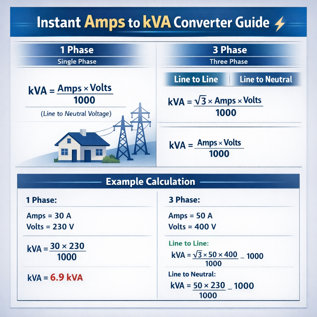
kVA denotes apparent power in kilo-volt-amperes. Apparent power S relates voltage and current without phase-angle correction; real power (kW) includes power factor. For single-phase systems apparent power S (kVA) equals V × I divided by 1000. For balanced three-phase systems, apparent power S (kVA) equals √3 × V_LL × I_line divided by 1000 when using line-to-line voltage.
Primary formulas (HTML only)
Single-phase apparent power:
Three-phase apparent power using line-to-line voltage:
Three-phase apparent power using phase (line-to-neutral) voltage and phase current:
Relationship between line-to-line and line-to-neutral:
To convert instantaneous Amps (I_inst) measured at one instant to kVA using instantaneous voltage (V_inst):
Explanation of variables and typical values
- V or V_phase (V): Phase voltage (line-to-neutral). Typical values: 120 V, 230 V, 240 V.
- V_LL (V): Line-to-line voltage (three-phase). Typical values: 208 V, 400 V, 415 V, 480 V.
- I or I_line (A): Instantaneous line current measured by ammeter or sensor. Typical ranges: 0.1 A (control circuits) to thousands of amps (industrial feeders).
- S (kVA): Apparent power in kilo-volt-amperes.
- √3: Square root of three ≈ 1.73205 (used for conversion between phase and line quantities in balanced three-phase).
- Power factor (pf): cos(ϕ), dimensionless (0–1). Typical industrial values: 0.8 to 0.95.
Single-phase (1 phase) instantaneous Amps to kVA conversion
Single-phase systems are the most straightforward: instantaneous kVA is the product of instantaneous voltage and instantaneous current divided by 1000. For practical measurements you may average instantaneous sample products over a specified interval to derive mean apparent power.
Single-phase formula and instrumentation
Explanation:
- V is instantaneous line voltage (V).
- I is instantaneous current (A).
- Divide by 1000 to convert VA to kVA.
Typical instrumentation: True-RMS meters or data acquisition that capture V_inst and I_inst synchronized to compute instantaneous VA = V_inst × I_inst. Use sampling rates consistent with the highest relevant harmonic or transient frequency (e.g., ≥2 kHz for power quality; higher for fast transients).
| Voltage (V) | Current (A) | Apparent Power (kVA) |
|---|---|---|
| 120 | 1 | 0.120 |
| 120 | 10 | 1.200 |
| 120 | 100 | 12.000 |
| 230 | 1 | 0.230 |
| 230 | 10 | 2.300 |
| 230 | 100 | 23.000 |
| 240 | 10 | 2.400 |
| 240 | 50 | 12.000 |
Three-phase (3 phase) instantaneous Amps to kVA conversion
Three-phase systems require careful identification of whether the provided voltage is line-to-line (V_LL) or line-to-neutral (V_LN). For balanced loads, two equivalent formulas apply; both yield identical S when values are used consistently.
Three-phase formula options
Where V_phase = V_LL / √3 and I_phase = I_line for Y-connected balanced loads.
Line-to-line vs Line-to-neutral practical notes
- If an instrument reports 400 V nominal, verify whether this is LL (common in IEC regions) or LN (less common). 400 V is typically LL and corresponds to 230 V LN.
- For delta-connected loads, current relationships change: line current is different from phase winding current. Use connection-specific relations (delta: I_line = √3 × I_phase for certain configurations).
- Unbalanced systems require per-phase calculation and summation of complex powers or use three-phase instantaneous power algorithms (sum of instantaneous per-phase VA values).
| System | V_LL (V) | V_LN (V) | Example I_line (A) | Result S (kVA) |
|---|---|---|---|---|
| IEC Commercial | 400 | 230 | 10 | 6.928 |
| IEC Industrial | 400 | 230 | 100 | 69.282 |
| North America | 480 | 277 | 10 | 8.317 |
| North America | 480 | 277 | 100 | 83.138 |
| North America | 208 | 120 | 50 | 17.994 |
| North America | 208 | 120 | 100 | 35.989 |
Power factor, phase angle, and conversion to kW
Instant Amps to kVA conversion yields apparent power. Real power (kW) equals apparent power multiplied by the power factor. For instantaneous values, instantaneous power factor can be computed from instantaneous voltage and current waveforms using synchronous sampling and phase detection.
Where pf = cos(ϕ), ϕ is the phase angle between fundamental components of voltage and current.
HTML formula examples for power factor
Example: If S = 50 kVA and pf = 0.88, then P = 50 × 0.88 = 44 kW.
Instantaneous measurement best practices and instrumentation
- Use true-RMS voltage and current sensors when harmonics are present; simple averaging methods are insufficient for non-sinusoidal waveforms.
- Synchronize voltage and current sampling to compute instantaneous VA = V_inst × I_inst and average over a defined time window for apparent power.
- Choose proper current transducers: CTs for high currents (ratio selection to minimize burden error) or Rogowski coils for very fast transients and wide bandwidth.
- Consider instrument burden, bandwidth, phase shift, and accuracy class (e.g., IEC 61869-2 and IEC 61869-3 for instrument transformers).
- For portable measurements, verify meter calibration and use appropriate clamps to avoid measurement errors caused by sensor orientation or partial conductor capture.
Transformer and generator sizing with instantaneous ampere to kVA conversions
Sizing transformers or generators requires converting measured or expected currents to kVA and adding margins for overload, inrush, harmonics, and ambient conditions. For three-phase equipment, calculate three-phase kVA using the formulas above and apply manufacturer recommendations and standards for continuous and short-time ratings.
Design checks and rules of thumb
- Apply a continuous service factor (e.g., 1.0 for continuous, 1.25 for 30 minute ratings depending on equipment specifications).
- Account for harmonic heating by applying K-factor or derating per IEEE/ANSI standards where non-linear loads dominate.
- For generator sizing include starting currents for motors: motor starting kVA can be several times running kVA depending on starting method (direct-on-line or soft-start).
- Use per-unit and short-circuit studies to ensure protective device coordination and voltage regulation under expected load kVA.
Detailed worked examples (real cases)
The following examples demonstrate step-by-step conversion of instantaneous current measurements into kVA for both single-phase and three-phase systems, including line-to-line and line-to-neutral considerations.
Example 1 — Single-phase instant measurement for an industrial heater
Scenario: An instantaneous current sensor reports 85.3 A on a single-phase 240 V circuit feeding a resistive heating element. Determine apparent power (kVA) and real power (kW) assuming pf = 1 (resistive).
- Identify parameters:
- V = 240 V
- I_inst = 85.3 A
- pf = 1.0
- Compute apparent power:S (kVA) = (V × I) / 1000S = (240 × 85.3) / 1000S = 20,472 / 1000 = 20.472 kVA
- Compute real power:P (kW) = S (kVA) × pf = 20.472 × 1.0 = 20.472 kW
- Interpretation and equipment sizing:
- Round or include margin: specify transformer minimum 25 kVA to allow some headroom and compliance with continuous loading rules.
- If ambient/high duty, consult thermal rating and use a larger transformer if necessary.
Example 2 — Three-phase instantaneous line current measured on a 480 V line-to-line distribution feeder
Scenario: A line current clamp measures 120 A on each phase of a balanced three-phase feeder where system voltage is specified as 480 V line-to-line. Determine apparent power S (kVA) and expected real power (kW) using a measured power factor pf = 0.92 lagging.
- Identify parameters:
- V_LL = 480 V
- I_line = 120 A
- pf = 0.92
- Compute three-phase apparent power:S (kVA) = (√3 × V_LL × I_line) / 1000
Use √3 ≈ 1.73205
S = (1.73205 × 480 × 120) / 1000Intermediate: 1.73205 × 480 = 831.384; × 120 = 99,766.08S = 99,766.08 / 1000 = 99.766 kVA - Compute real power:P (kW) = S (kVA) × pf = 99.766 × 0.92 = 91.7827 kW
- Interpretation:
- A 125 kVA transformer would provide modest margin; consider motor starting and harmonic derating.
- Verify protective device ampacity: continuous current at 100% loading is 120 A; device selection per NEC or local code typically uses a multiplier (e.g., 125% for continuous loads).
Example 3 — Three-phase line-to-neutral calculation and LL/LN verification
Scenario: A measurement system provides phase voltage 230 V (line-to-neutral) and phase current 45 A per phase in a balanced Y-connected load. Calculate S (kVA) and verify equivalent calculation using V_LL and I_line.
- Parameters:
- V_phase = 230 V
- I_phase = 45 A
- Compute S using phase formula:S = (3 × V_phase × I_phase) / 1000S = (3 × 230 × 45) / 10003 × 230 = 690; × 45 = 31,050S = 31.05 kVA
- Compute equivalent using V_LL:V_LL = V_phase × √3 = 230 × 1.73205 = 398.372 V (≈400 V standard)S = (√3 × V_LL × I_line) / 1000 = (1.73205 × 398.372 × 45) / 1000Calculate intermediate: 1.73205 × 398.372 ≈ 689.999 (≈690); × 45 = 31,050 → S = 31.05 kVA
- Conclusion: Both methods agree if conversion is consistent.
Extensive lookup tables for common voltages and currents
The following tables provide precomputed apparent power values for common voltages and a set of representative currents. These are useful for quick sizing and verification in design documents and protective device coordination tables.
| System | Voltage | Current (A) | kVA (single-phase) | kVA (three-phase) |
|---|---|---|---|---|
| 120/1ϕ | 120 V | 5 | 0.600 | — |
| 120/1ϕ | 120 V | 10 | 1.200 | — |
| 230/1ϕ | 230 V | 10 | 2.300 | — |
| 230/1ϕ | 230 V | 32 | 7.360 | — |
| 400/3ϕ | 400 V LL | 10 | — | 6.928 |
| 400/3ϕ | 400 V LL | 50 | — | 34.641 |
| 400/3ϕ | 400 V LL | 100 | — | 69.282 |
| 480/3ϕ | 480 V LL | 10 | — | 8.317 |
| 480/3ϕ | 480 V LL | 75 | — | 62.378 |
| 480/3ϕ | 480 V LL | 200 | — | 166.276 |
| 208/3ϕ | 208 V LL | 30 | — | 10.818 |
| 208/3ϕ | 208 V LL | 100 | — | 36.0 |
| Phase Voltage (V) | Line Voltage (V_LL) | Current (A) | kVA (3φ computed) |
|---|---|---|---|
| 120 | 208 | 20 | 4.160 |
| 230 | 400 | 20 | 13.860 |
| 230 | 400 | 40 | 27.720 |
| 277 | 480 | 20 | 15.221 |
| 277 | 480 | 100 | 76.106 |
| 240 | 415 | 75 | 53.990 |
Unbalanced systems and per-phase instantaneous calculations
When phases are unbalanced, compute instantaneous apparent power per phase and sum as complex quantities (S_total = S_A + S_B + S_C) if phase angles are known, or sum instantaneous VA samples for each phase and average. For protection and thermal limits, use the highest per-phase apparent power for conductor and equipment sizing.
Procedure for unbalanced instantaneous data
- Capture synchronous instantaneous voltage and current per phase: V_A(t), I_A(t), V_B(t), I_B(t), V_C(t), I_C(t).
- Compute instantaneous VA per phase: VA_A(t) = V_A(t) × I_A(t), similarly for B and C.
- Average each instantaneous VA over the measurement window to obtain mean apparent VA per phase.
- Convert to kVA by dividing by 1000 and, if necessary, compute resultant complex sum using RMS voltages and phasor currents for precise complex power (requires phasor extraction).
Standards, normative references, and authoritative resources
Use recognized standards and manufacturer guidance when applying instantaneous Amps to kVA conversions in design, testing, and compliance work. Key normative references include:
- IEC 60038 — Standard Voltages: defines standard nominal voltages for low and high voltage systems. See https://www.iec.ch
- IEC 61869 series — Instrument transformers: performance and accuracy classes for CTs and VTs. See https://www.iec.ch
- IEEE Std 1459 — Definitions for power in systems with nonsinusoidal waveforms (useful for power and harmonic definitions). See https://standards.ieee.org
- NFPA 70 (NEC) — Electrical code covering conductor ampacity, overcurrent protection, and equipment installation in the USA. See https://www.nfpa.org
- NEMA MG 1 and generator/transformer manufacturer datasheets — guidance on ratings, loading, and thermal limitations. See https://www.nema.org
- IEC/IEEE guidelines for power quality and measurements — for accurate instantaneous measurement techniques
Practical pitfalls and mitigation strategies
- Incorrect voltage reference: Always confirm whether meters report LL or LN values before applying √3 factors.
- Non-sinusoidal waveforms: Use true-RMS instruments and compute apparent power from instantaneous samples; do not rely solely on fundamental approximations.
- CT saturation: Avoid high DC offsets and ensure CT ratio and burden are selected to prevent measurement distortion at high currents.
- Sampling aliasing: Choose sampling rate > 2x highest harmonic of interest (preferably > 10× for power quality analysis) and apply antialiasing where required.
- Harmonic heating: Use K-factor ratings or IEEE harmonic derating procedures to size transformers under non-linear loads.
SEO and practical keyword guidance for specification documents
When preparing technical documents, datasheets, or web content covering Instant Amps To Kva Converter, 1 Phase, 3 Phase, Line To Line, Line To Neutral, include:
- Clear usage of keywords in headings and first 200 words.
- Tables of common voltages and currents for quick lookup.
- Worked examples for the most common configurations: single-phase 120/240 V and three-phase 208/400/480 V.
- Reference to relevant standards (IEC, IEEE, NFPA) and authoritative links for credibility.
Final technical notes and verification checklist
- Confirm measurement type: instantaneous vs RMS; adapt formulas accordingly.
- Identify whether voltage is LL or LN before applying √3 conversions.
- Use per-phase calculations for unbalanced systems and sum complex powers as required.
- Apply power factor when converting from kVA to kW.
- Follow instrument and transformer datasheet accuracy limits when reporting results.
- Cross-check quick table lookups with full calculations for critical equipment sizing.
For authoritative standard purchases, visit IEC (https://www.iec.ch), IEEE (https://standards.ieee.org), NFPA (https://www.nfpa.org), and NEMA (https://www.nema.org). Manufacturer application notes from major transformer and meter vendors provide pragmatic derating and measurement details.