This article provides a precise screening calculator for transformer secondary conductor sizing and verification requirements.
Instant results derive from full load current inputs, adjustments, corrections, and short-circuit considerations environmental factors
Transformer Secondary Conductor Size Screening Calculator (from Full-Load Current)
Overview of Transformer Secondary Conductor Screening
Selecting transformer secondary conductors requires rapid, precise screening to translate transformer kVA and system voltage into conductor requirements. This article presents a technical workflow and formulas that yield instant results from full load current, including correction and derating factors.We treat transformer secondary conductors as a system-design problem: convert transformer rating to full load current, apply continuous-load and grouping multipliers, correct for ambient temperature and insulation ratings, check voltage drop, and verify short-circuit and protection coordination. The objective is a deterministic screening calculator that outputs candidate conductor sizes or the number of parallel runs required for compliance with design targets and standards.Key Inputs and Outputs for an Instant Screening Calculator
- Inputs:
- Transformer apparent power (kVA) and secondary nominal voltage (V).
- Connection type: single-phase or three-phase; grounded wye or delta.
- Maximum allowable voltage drop (percentage or volts) and circuit length (m or ft).
- Conductor material (copper or aluminum) and insulation temperature rating (e.g., 75°C, 90°C).
- Ambient temperature and cable grouping (number of conductors in conduit or tray).
- Expected continuous percentage of load and motor starting or short-duration loads.
- Outputs:
- Full Load Current (A).
- Required ampacity after continuous or demand factors (A).
- Candidate conductor size(s) and number of parallels.
- Estimated voltage drop and percentage.
- Short-circuit prospective checks and time-current coordination notes.
Fundamental Electrical Formulas
Three-phase full load current (A):
Single-phase full load current (A):
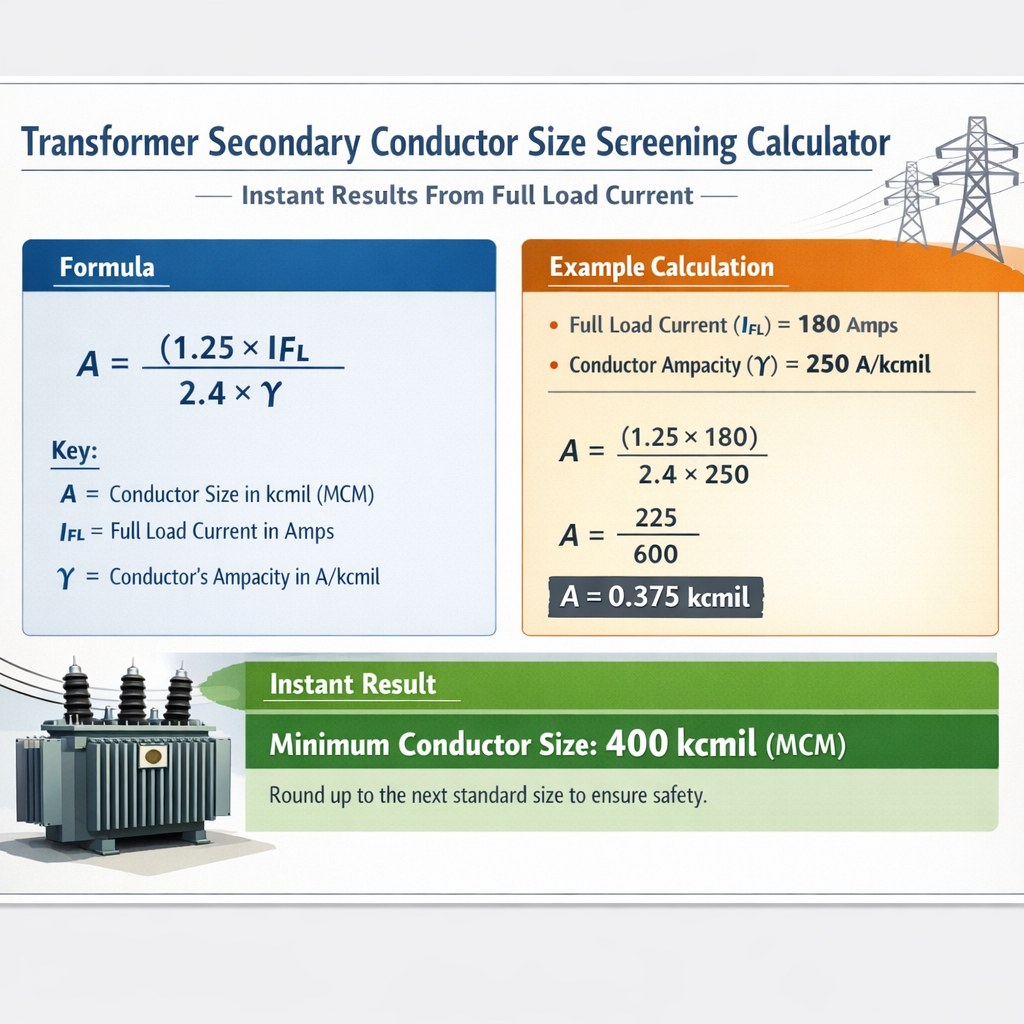
Required conductor ampacity for continuous load (NEC-style 125% rule):
Voltage drop for three-phase circuits (approximate):
Or approximate resistive-only voltage drop percentage:
Variable explanations and typical values
- kVA: Apparent power rating of transformer in kilovolt-amperes (typical values: 15 kVA to 2000 kVA+).
- V: Line-to-line RMS voltage for three-phase systems (typical values: 208 V, 400 V, 480 V, 600 V).
- √3: Square root of three ≈ 1.732.
- I: Full load current in amperes (A).
- A_required: Minimum conductor ampacity necessary after continuous load multiplier and corrections.
- F_group: Grouping factor (≤1) from cable bundling tables (e.g., 0.7–1.0 depending on number of conductors and installation method).
- F_temp: Temperature correction factor for conductor insulation rating (e.g., 0.82 at 40°C for 75°C rated insulation; consult standard tables).
- R, X: Circuit resistance and reactance per unit length (Ω/m or Ω/ft) for chosen conductor and installation.
- L: One-way conductor length (m or ft) between transformer secondary and load or point of interest.
- cosφ: Power factor (typical 0.8–1.0 for general balanced loads; motor loads often 0.8).
Lookup Table — Transformer kVA to Full Load Current (Three-Phase)
| Transformer kVA | I at 208 V (A) | I at 240 V (A) | I at 400 V (A) | I at 480 V (A) | I at 600 V (A) |
|---|---|---|---|---|---|
| 15 | 41.6 | 36.1 | 21.6 | 18.0 | 14.4 |
| 30 | 83.1 | 72.1 | 43.3 | 36.1 | 28.9 |
| 75 | 207.7 | 180.4 | 108.3 | 90.1 | 72.1 |
| 150 | 415.5 | 360.8 | 216.5 | 180.2 | 144.1 |
| 250 | 692.5 | 602.5 | 361.6 | 301.8 | 241.5 |
| 500 | 1385.0 | 1205.1 | 723.2 | 603.6 | 483.0 |
| 750 | 2077.5 | 1807.6 | 1084.9 | 905.4 | 724.5 |
| 1000 | 2770.0 | 2410.2 | 1446.4 | 1207.2 | 966.0 |
Notes: Values shown are computed using I = (kVA × 1000) / (√3 × V). Use these as immediate screening results for conductor sizing.
Typical Conductor Ampacity Tables (Representative Values)
The following tables present typical continuous ampacity values for commonly used cable cross-sectional areas (copper and aluminum). These are representative and must be confirmed against the code (e.g., NEC Table 310.16) and installation method.
| Copper cross-section (mm²) | Typical ampacity (A) @ 75°C |
|---|---|
| 16 | 76 |
| 25 | 101 |
| 35 | 125 |
| 50 | 158 |
| 70 | 198 |
| 95 | 237 |
| 120 | 269 |
| 150 | 308 |
| 185 | 348 |
| 240 | 417 |
| 300 | 515 |
| 400 | 676 |
| 500 | 810 |
| 630 | 999 |
| Aluminium cross-section (mm²) | Typical ampacity (A) @ 75°C |
|---|---|
| 35 | 105 |
| 50 | 135 |
| 70 | 175 |
| 95 | 215 |
| 120 | 250 |
| 150 | 290 |
| 185 | 330 |
| 240 | 390 |
| 300 | 460 |
| 400 | 600 |
| 500 | 760 |
These ampacities are for estimating and screening only. Actual allowable ampacities per regulation depend on installation method, insulation type, and ambient conditions.
Screening Algorithm: Step-by-step Workflow
- Compute full load current (I) using the formula for single‑ or three‑phase systems.
- Decide if the load is continuous. If continuous, multiply I by 1.25 (125%).
- Apply grouping (F_group) and ambient temperature correction (F_temp) factors: A_required = I × 1.25 × F_group × F_temp.
- Select candidate conductor(s) whose tabulated ampacity ≥ A_required for the conductor insulation temperature column appropriate to the termination rating.
- Check voltage drop against design limit (commonly 1.5% for branch circuits, 3% for feeder + branch total). Compute V_drop and VD%.
- If VD% > limit, increase conductor size or use parallel conductors, or reduce length.
- Verify short-circuit withstand: conductor short-circuit temperature and protective device clearing times; consult IEC/IEEE/NEC rules.
- Finalize and document assumptions: ambient, grouping, conductor type, parallel runs, and reference normative clauses.
Correction and Derating Factors — Practical Values
- Temperature correction factor (F_temp): Typical values:
- At 30°C: ~1.00 for 75°C-rated conductor.
- At 40°C: ~0.91–0.95 depending on table.
- At 50°C: ~0.82 for 75°C-rated conductors.
- Grouping factor (F_group): Depends on number of current-carrying conductors and conduit/tray configuration. Common screening values: 1.0 (single), 0.8–0.9 (small group), 0.7 (large bundle).
- Altitude correction: above 1000 m altitude may require derating (refer to local code).
- Terminal temperature limitation: Terminations may be limited to 75°C maximum even if conductor ampacity table is for 90°C. Use the lower column when necessary.
Voltage Drop Calculation Details
For instantaneous screening, use a resistive approximation sufficient for copper and aluminum where reactance is small or where conductor length is modest.
Resistive voltage drop (three‑phase) in volts, assuming R_total is roundtrip conductor resistance per meter and one‑way length L (m):
Where R_total (Ω/m) is the conductor resistance per meter for the chosen cross-section at operating temperature. To compute percentage voltage drop:
Typical DC resistance at 20°C (example assumptions for screening):
- Copper 500 mm²: R ≈ 0.00008 Ω/m
- Copper 300 mm²: R ≈ 0.00012 Ω/m
- Aluminium 300 mm²: R ≈ 0.00020 Ω/m
These resistance values are representative; use manufacturer cable tables for exact R and temperature correction.
Example 1 — Detailed Case (Copper conductors)
Problem statement:
- Transformer rating: 500 kVA three-phase
- Secondary voltage: 480 V (line-to-line)
- Load condition: Continuous (100% continuous)
- Conductor material: Copper, insulation rating 75°C
- Ambient temperature: 30°C (no temperature correction assumed for screening)
- Circuit length: 40 meters (one-way)
- Allowed voltage drop: 3% (overall feeder + branch permitted)
- Cable grouping: single run per phase in conduit (F_group = 1.0)
Use the three-phase formula:
From the copper ampacity table, a 500 mm² copper conductor has a typical ampacity ≈ 810 A @ 75°C, which exceeds 751.9 A. Therefore, a single 500 mm² copper per phase is acceptable from an ampacity perspective and termination rating permitting.
Step 5 — Voltage drop estimate (simplified resistive):Assume resistive DC R ≈ 0.00008 Ω/m for 500 mm² copper (representative). For three-phase:
- Full load current: 601.5 A
- Required ampacity after continuous multiplier: 751.9 A
- Selected conductor: Copper 500 mm² (ampacity ≈ 810 A)
- Estimated voltage drop: 3.334 V (0.7%), well under 3% limit
- Confirm 500 mm² termination compatibility on transformer and switchgear.
- Validate exact conductor R and X from manufacturer; refine VD calculation with reactance if longer runs or harmonic-rich loads.
- Verify short-circuit withstand and protective device settings with supplier curves.
Example 2 — Detailed Case (Aluminium conductors and paralleled cables)
Problem statement:
- Transformer rating: 150 kVA three-phase
- Secondary voltage: 208 V (line-to-line)
- Load condition: 100% continuous
- Conductor material: Aluminium, limited to standard mm² sizes
- Ambient temperature: 40°C (apply temperature correction)
- Circuit length: 30 m one-way
- Allowed voltage drop: 3% total
A_required = 520.4 / 0.91 = 572.0 A (we divide by factor if tabular ampacity is reduced — alternative formulation: A_required = 520.4 × (1/F_temp) when using table values that must be multiplied by F_temp; many tables use multiplication less than 1: to be consistent, treat A_required = 520.4 / F_temp).
Step 4 — Candidate selection from aluminium ampacity table:From table, a single 500 mm² aluminium conductor shows typical ampacity ≈ 760 A (representative). However, consider practical availability: 300 mm² Al ≈ 460 A (insufficient), 400 mm² Al ≈ 600 A (marginally sufficient depending on exact tabulated values and F_temp). To be conservative and allow for future margin, one may choose either:
- Single 400 mm² aluminium per phase if manufacturer ampacity at 75°C and correction yields ≥ 572 A; or
- Two parallel 240 mm² aluminium conductors per phase (each 240 mm² ≈ 390 A typical; two parallels share current → combined rating ≥ 780 A and provide redundancy).
Assume R ≈ 0.00020 Ω/m for 240 mm² aluminium (per conductor). When two conductors are paralleled per phase, effective resistance halves: R_effective = 0.00010 Ω/m.
- Full load current: 416.3 A
- Required ampacity after continuous and temperature correction: ≈ 572 A
- Single 400 mm² Al may be marginal; two parallel 240 mm² Al per phase provide combined ampacity > 572 A and voltage drop ≈1.04%.
- Parallel conductor design must follow code rules for paralleled conductors (equal length, same material, same type and insulation, same lay, and same manufactured type).
- Terminate paralleled conductors appropriately and verify busbar/terminal sizes.
- Confirm exact aluminium ampacity tables and temperature correction factors from the regulating authority or manufacturer data.
Short-Circuit and Protective Device Considerations
- Ensure conductor short-circuit rating is adequate for the maximum prospective fault current and clearing time. Use adiabatic heating equation or manufacturer short-circuit ratings:
k = I_fault × √t ≤ k_s where k_s is conductor-specific constant, or explicitly use tables providing I^2t withstand.
- Coordinate protective devices so that conductor clearing time does not allow excessive heating. Reference IEEE and IEC protective device coordination principles.
- Verify fuse/CB interrupting capacity and transformer inrush characteristics when choosing upstream protection.
Standards, Normative References and Authoritative Links
- NFPA 70 (National Electrical Code) — conductor ampacity, ampacity correction and continuous-load rules: https://www.nfpa.org/nec
- IEC 60076 — Power transformers — general standard for transformer ratings and testing: https://www.iec.ch
- IEEE C57 series — Transformer standards and ratings: https://standards.ieee.org
- IEC 60287 — Electric cables — calculation of the continuous current rating (ampacity): https://www.iec.ch/
- British Standard BS 7671 (IET Wiring Regulations) — for UK wiring practices: https://www.theiet.org/publishing/bs-7671/
These references should be consulted for specific local regulatory requirements and the authoritative ampacity and derating tables applicable to your jurisdiction.
Implementation Notes for a Screening Calculator
A practical instant-results screening calculator must:
- Accept kVA and voltage inputs and compute FLC instantly using the formulas above.
- Provide configurable parameters: continuous (%) flag, ambient temperature, grouping, conductor material and insulation rating, accepted voltage drop limit, and conductor length.
- Use internal lookup tables for conductor ampacity and resistance per unit length by size and material, referencing manufacturer tables and normative tables.
- Automatically evaluate parallel runs if single conductor size cannot meet ampacity or if a voltage drop constraint forces upsizing.
- Output candidate solutions with rationale and display the governing formulas and variable values for auditability.
Validation and Practical Recommendations
- Always validate screening results against local code tables and manufacturer data. Screening calculators are an engineering aid, not a substitute for final design checks.
- Document all assumptions: ambient, grouping, insulation rating, calculation method used for VD (resistive or full R+jX), and any rounding rules.
- For installations with motors or non-linear loads, consider inrush currents, harmonic heating, and verify cable thermal behavior under harmonic distortion using standards such as IEC 60287 and IEC 60502.
- When paralleling conductors, follow code provisions strictly including identical conductor types and lengths.
Appendix — Quick Reference Formulas and Constants
| Quantity | Formula / Typical value |
|---|---|
| Three-phase full load current | I = (kVA × 1000) / (√3 × V) |
| Single-phase full load current | I = (kVA × 1000) / V |
| Continuous-load multiplier | 1.25 (125%) typical for continuous loads per many codes |
| Typical √3 | 1.732 |
| Voltage drop three-phase | V_drop = √3 × I × R × L |
| Example R for Cu 500 mm² | ~0.00008 Ω/m (representative) |
Final Engineering Checklist
- Confirm full load currents per transformer nameplate and actual operating voltage.
- Identify continuous load percentage and apply appropriate multipliers.
- Select conductor sizes from authoritative ampacity tables for the installation method and conductor temperature rating.
- Apply ambient and grouping correction factors using normative tables.
- Perform voltage drop calculation and iterate conductor size or parallel runs until limits are met.
- Check short-circuit heating I^2t against conductor limits and protective device timing.
- Document references, assumptions, and selected solution for compliance and review.
- NFPA 70, National Electrical Code (NEC) — https://www.nfpa.org/nec
- IEC 60076 — Power transformers — https://www.iec.ch
- IEC 60287 — Electric cables — calculation of current ratings — https://www.iec.ch
- IEEE Standards — Transformer and switchgear standards — https://standards.ieee.org
- IET Wiring Regulations (BS 7671) — https://www.theiet.org/publishing/bs-7671/