Instant reactive power conversion simplifies capacitor sizing and power system optimization tasks worldwide for engineers.
Calculate kvar from kW and power factor in seconds with reliable formulas and practical accuracy.Instant Reactive Power Calculator – Compute kVAr from kW and Power Factor
Technical background and objective
The objective of an Instant Reactive Power Calculator is to convert active power (kW) and power factor (pf) into reactive power (kvar) rapidly and reliably for design, commissioning, and operational decisions. This function is core to capacitor bank sizing, automatic power factor correction (APFC) control logic, and real-time energy management systems.
Why kW, kVAR and power factor matter
Active power (kW) performs useful work. Reactive power (kvar) sustains magnetic and electric fields in inductive or capacitive equipment. Power factor (pf) is the cosine of the phase angle between voltage and current and indicates the proportion of apparent power (kVA) that is active.
- Operators need quick conversion to size capacitors and avoid penalties for poor pf.
- Protection and stability engineers require kvar estimates for relay settings and fault analysis.
- Facility managers use instant calculations for demand charge optimization and APFC control.
Core formulas and derivations
Presenting the core mathematical relationships used by an instant converter. Formulas are shown using plain HTML text and common math functions available in calculators or programming languages.
Fundamental relationships
Apparent power S, active power P and reactive power Q are related as:
Power factor is defined as:
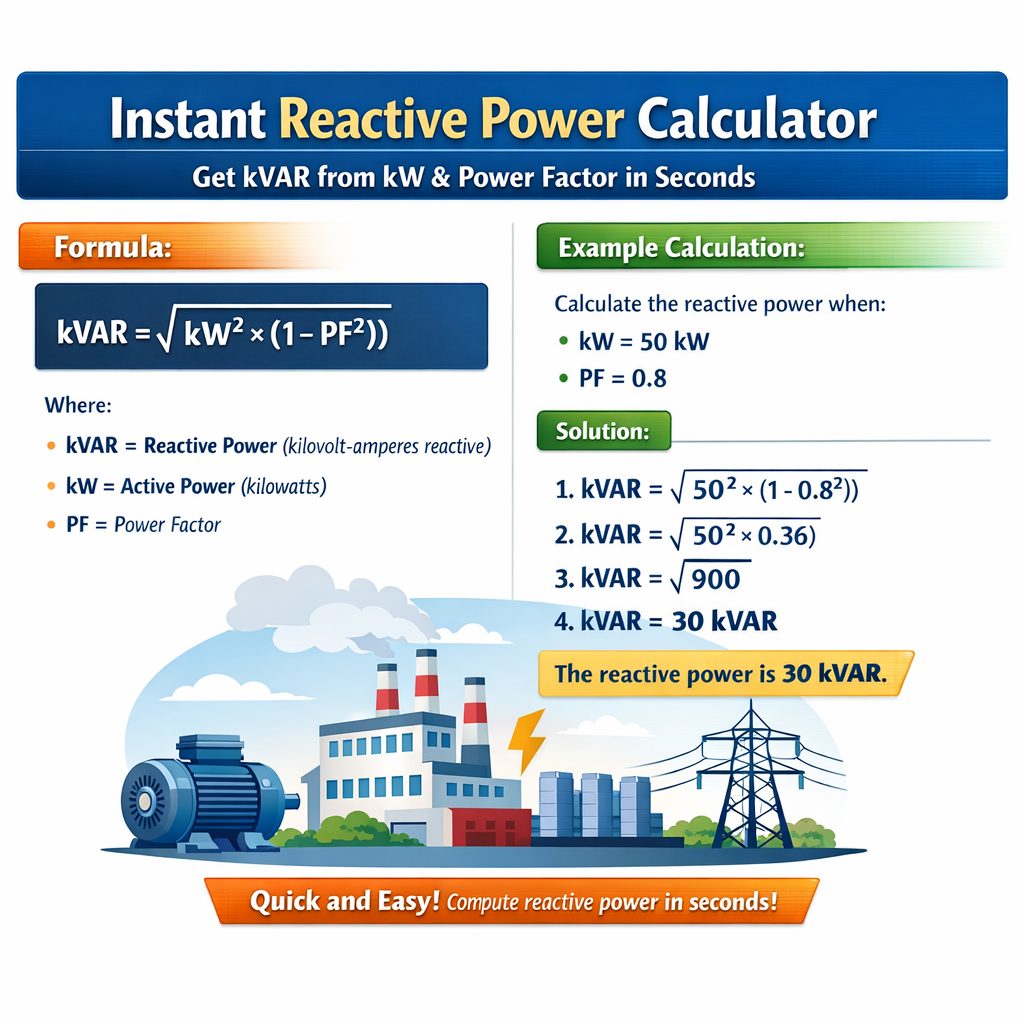
Reactive power Q (in kvar) can be expressed directly from P and pf:
Alternatively, solving from S:
Variable explanations and typical ranges
- P (kW): Active power delivered to loads. Typical industrial values: 1 kW to several MW. Examples: small motor 5 kW, factory floor 500 kW.
- pf (unitless, 0-1): Power factor, usually lagging for inductive loads. Typical values: 0.6 (poor) to 0.98 (excellent). Utilities often require pf > 0.95.
- Q (kvar): Reactive power required or supplied. Can be positive (inductive demand) or negative (capacitive supply). Typical correction steps: 5 kvar to hundreds of kvar per bank.
- S (kVA): Apparent power. Used when scaling transformer ratings or cables.
Note on units: Keep P in kW and Q in kvar for direct multiplication; if P is in watts, divide by 1000 first.
Computation steps used in instant calculators
- Validate inputs: P >= 0, 0 < pf <= 1. If pf <= 0 or >1 flag invalid input.
- Compute phi = arccos(pf) in radians (or degrees if calculator is configured).
- Compute tan(phi) to obtain Q factor.
- Compute Q (kvar) = P (kW) * tan(phi).
- Round results according to desired resolution (e.g., 0.01 kvar for precision equipment).
Edge cases and sign convention
- If pf is leading (capacitive), a negative Q indicates net capacitive delivery. Many calculators accept a leading/lagging flag.
- When pf is 1.0, tan(arccos(1)) = 0 so Q = 0 (purely resistive).
- When pf is very small (e.g., 0.1), Q rises steeply; ensure numeric stability in the arccos and tan steps.
Tables of common conversions for quick reference
The following tables present precomputed Q (kvar) for common kW values and power factors to facilitate rapid lookup during commissioning or plant operations.
| kW | pf=0.60 | pf=0.70 | pf=0.80 | pf=0.85 | pf=0.90 | pf=0.95 | pf=0.98 | pf=1.00 |
|---|---|---|---|---|---|---|---|---|
| 10 | 13.33 | 10.20 | 7.50 | 6.99 | 4.84 | 3.29 | 2.04 | 0.00 |
| 25 | 33.33 | 25.51 | 18.75 | 17.48 | 12.11 | 8.22 | 5.10 | 0.00 |
| 50 | 66.67 | 51.02 | 37.50 | 34.97 | 24.21 | 16.45 | 10.20 | 0.00 |
| 100 | 133.33 | 102.04 | 75.00 | 69.94 | 48.42 | 32.90 | 20.40 | 0.00 |
| 250 | 333.33 | 255.10 | 187.50 | 174.86 | 121.06 | 82.25 | 51.00 | 0.00 |
| 500 | 666.67 | 510.20 | 375.00 | 349.72 | 242.11 | 164.50 | 102.00 | 0.00 |
Table notes: Values rounded to two decimal places. Calculation uses Q = P * tan(arccos(pf)). Example: for P=100 kW and pf=0.9, phi=arccos(0.9)=25.84°, tan(phi)=0.484, Q=48.42 kvar.
| pf | phi (deg) | tan(phi) | Q per 1 kW (kvar) | Q per 100 kW (kvar) |
|---|---|---|---|---|
| 0.50 | 60.00 | 1.7321 | 1.7321 | 173.21 |
| 0.60 | 53.13 | 1.3333 | 1.3333 | 133.33 |
| 0.70 | 45.57 | 1.0206 | 1.0206 | 102.06 |
| 0.80 | 36.87 | 0.7500 | 0.7500 | 75.00 |
| 0.85 | 31.79 | 0.6991 | 0.6991 | 69.91 |
| 0.90 | 25.84 | 0.4843 | 0.4843 | 48.43 |
| 0.95 | 18.19 | 0.3294 | 0.3294 | 32.94 |
| 0.98 | 11.48 | 0.0204 | 0.0208 | 2.04 |
| 1.00 | 0.00 | 0 | 0 | 0 |
Practical calculation examples with full development
Example 1 — Industrial motor load correction
Scenario: A facility operates a 350 kW motor bank with an operating power factor of 0.78 lagging. The goal is to determine the reactive power required to correct the plant power factor to 0.95 lagging.
Step 1 — Determine initial reactive power Q1:
Use Q1 = P * tan(arccos(pf1)).
Compute phi1 = arccos(0.78) = ...
Detailed numeric steps:
- P = 350 kW.
- pf1 = 0.78. Compute phi1 = arccos(0.78). Numerically phi1 ≈ 38.73 degrees.
- tan(phi1) ≈ tan(38.73°) = 0.8003.
- Q1 = 350 * 0.8003 = 280.10 kvar (existing inductive demand).
- pf2 = 0.95. phi2 = arccos(0.95) ≈ 18.19 degrees.
- tan(phi2) ≈ 0.3294.
- Q2 = 350 * 0.3294 = 115.29 kvar (target inductive demand after correction).
Delta Q = 280.10 - 115.29 = 164.81 kvar.
Interpretation: A capacitor bank sized approximately 165 kvar (or arranged in standard steps summing to >=165 kvar) should be installed to raise pf from 0.78 to 0.95. Consideration must be given to switching transients, harmonic amplification, and protective device coordination.
Example 2 — Service contract penalty avoidance
Scenario: A commercial building has a measured demand of 120 kW with pf = 0.82 lagging. The utility applies a penalty when monthly average pf < 0.92. Compute kvar needed to meet pf target of 0.92.
Step-by-step:
- P = 120 kW.
- pf1 = 0.82 => phi1 = arccos(0.82) ≈ 34.86°; tan(phi1) ≈ 0.6954; Q1 = 120 * 0.6954 = 83.45 kvar.
- pf2 = 0.92 => phi2 = arccos(0.92) ≈ 23.07°; tan(phi2) ≈ 0.4258; Q2 = 120 * 0.4258 = 51.10 kvar.
- Required capacitor = Q1 - Q2 = 83.45 - 51.10 = 32.35 kvar.
Recommendation: Install a 35 kvar or 40 kvar staged capacitor bank with automatic switching. Include inrush limiting and detuning reactors if harmonic levels exceed thresholds.
Example 3 — Rapid handheld calculation for field engineers
Scenario: Field technician measures a lighting circuit with P=15 kW and pf=0.96. Wants to know Q quickly for logging.
Computation:
- P = 15 kW.
- pf = 0.96 => phi = arccos(0.96) ≈ 16.26°. tan(phi) ≈ 0.2919.
- Q = 15 * 0.2919 = 4.3785 kvar ≈ 4.38 kvar.
Note: Small kvar values may be managed with single-step capacitors in distribution panels.
Implementation guidance for instant calculators and embedded systems
Algorithmic considerations
- Use double-precision floating point arithmetic for arccos and tan to maintain accuracy across pf domain.
- Clamp pf inputs to (0.0001, 1.0) to avoid domain errors in arccos; provide error messaging for out-of-range values.
- Prefer arctangent-based identities in microcontrollers with limited trig libraries: tan(arccos(pf)) = sqrt(1 - pf^2) / pf. Thus Q = P * (sqrt(1 - pf^2) / pf).
Proof of identity using algebraic transformation:
Precision and rounding
- Round kvar values to the resolution matching hardware (e.g., 0.01 kvar for reporting, 1 kvar for bank sizing).
- When using the identity sqrt(1 - pf^2)/pf near pf=1, use numerically stable expansions or avoid subtractive cancellation by checking pf threshold.
Measurement and metering best practices
Accurate P and pf measurement is essential. Errors in pf directly translate into reactive power errors via the tangent function.
- Use true-rms meters for non-sinusoidal currents.
- Average pf over suitable time windows for billing-sensitive applications (e.g., 10-minute or billing cycle averages as specified by the utility).
- Record both lagging/leading signs and ensure consistent sign convention across systems.
Standards, regulations and authoritative references
Reactive power and power factor correction are governed by various international standards, grid codes and manufacturer recommendations. The following resources are authoritative:
- IEEE Std 141 (Green Book) — Electric power distribution for industrial plants. Available via IEEE: https://standards.ieee.org/standard/141-1993.html
- IEEE Std 1547 — Interconnection and interoperability of distributed energy resources with utility networks: https://standards.ieee.org/standard/1547-2018.html
- IEC 60871 / IEC 60871-1 — Capacitors for power electronics and power factor correction (subject to regional publication variants): https://www.iec.ch/
- U.S. Department of Energy guidance on power factor improvement and energy savings: https://www.energy.gov/eere/amo/power-factor-improvement
- NIST publications and guidance on power systems measurement best practices: https://www.nist.gov/
Ensure compliance with local grid codes which may specify acceptable pf ranges, measurement intervals, and penalties for poor pf.
Safety, harmonics and practical limitations
Installing capacitors or correcting pf without harmonic analysis can create resonance and amplify distortion. Follow these practical cautions:
- Perform harmonic spectrum analysis before adding significant kvar at low-order system frequencies.
- Consider detuned filters (e.g., 5% or 7% reactor detuning) for systems with substantial nonlinear loads.
- Coordinate switching devices (contactors, relays) to avoid simultaneous capacitor switching surges.
- Include overvoltage protection and ensure transformer kVA ratings accommodate reduced reactive flow.
Integration with automation and SCADA
Instant reactive power calculations are often embedded into PLCs, APFC controllers, and SCADA dashboards. Key integration points:
- Real-time acquisition of power (kW) and instantaneous pf from digital meters via Modbus, IEC 61850, or other protocols.
- Calculation module implementing Q = P * sqrt(1 - pf^2) / pf for speed and stability.
- Control logic to switch capacitor steps gradually and avoid hunting; hysteresis and time delays are essential.
- Data logging for validation and billing disputes: record pre/post correction P, Q, S, pf.
Additional lookup tables and sizing matrices
These matrices provide designers a quick method to select capacitor sizes in standard steps for common kW blocks and target pf improvements.
| kW | From pf 0.75 to 0.95 (kvar) | From pf 0.80 to 0.95 (kvar) | From pf 0.85 to 0.95 (kvar) | From pf 0.90 to 0.95 (kvar) |
|---|---|---|---|---|
| 25 | 58.72 | 26.53 | 12.45 | 6.02 |
| 50 | 117.44 | 53.06 | 24.90 | 12.05 |
| 100 | 234.88 | 106.12 | 49.80 | 24.10 |
| 200 | 469.76 | 212.24 | 99.60 | 48.20 |
| 500 | 1174.40 | 530.59 | 249.00 | 120.50 |
Table note: Values are Qrequired = P*(tan(arccos(pf_initial)) - tan(arccos(pf_target))). Rounded to two decimals.
SEO and implementation notes for web calculators
- Embed core formula text as plain HTML so search engines can index calculation methodology and variables.
- Provide structured data (schema.org) for tools if implementing an online calculator, enabling rich result snippets.
- Offer downloadable CSV/Excel tables so design engineers can import precalculated kvar lookup values into BOM or SLD documents.
- Index pages by keywords: "kvar from kW", "instant reactive power calculator", "power factor to kvar", "capacitor sizing kVAR".
Reference appendix and further reading
Key authoritative sources and further technical reading for advanced design and research:
- IEEE Power & Energy Society publications — technical papers on power factor, harmonic interactions, and APFC design: https://pes.ieee.org/
- IEC standards catalogue — capacitors and grid interconnection standards: https://www.iec.ch/standards
- U.S. Department of Energy — guides on reactive power and power factor: https://www.energy.gov/
- CIGRE reports on power quality and reactive power management: https://www.cigre.org/
Final operational checklist for field deployment
- Validate metering accuracy and sampling window for active power and pf.
- Calculate Q using stable numeric identity: Q = P * sqrt(1 - pf^2) / pf (or Q = P * tan(arccos(pf))).
- Assess harmonic content and decide detuning if THD > recommended thresholds.
- Stage capacitor steps and configure control hysteresis to prevent frequent switching.
- Document signed-off values for capacitor sizes, expected post-correction pf, and operational safety measures.
Using the formulas and tables contained in this article allows a practitioner to obtain kvar from kW and power factor in seconds, supporting design, commissioning and operational decisions across industrial and commercial power systems.