This article explains fast methods to calculate transformer secondary fault current including upstream impedance effects.
Procedures, formulas, tables, and worked examples provided for engineers performing protective coordination and fault analysis.
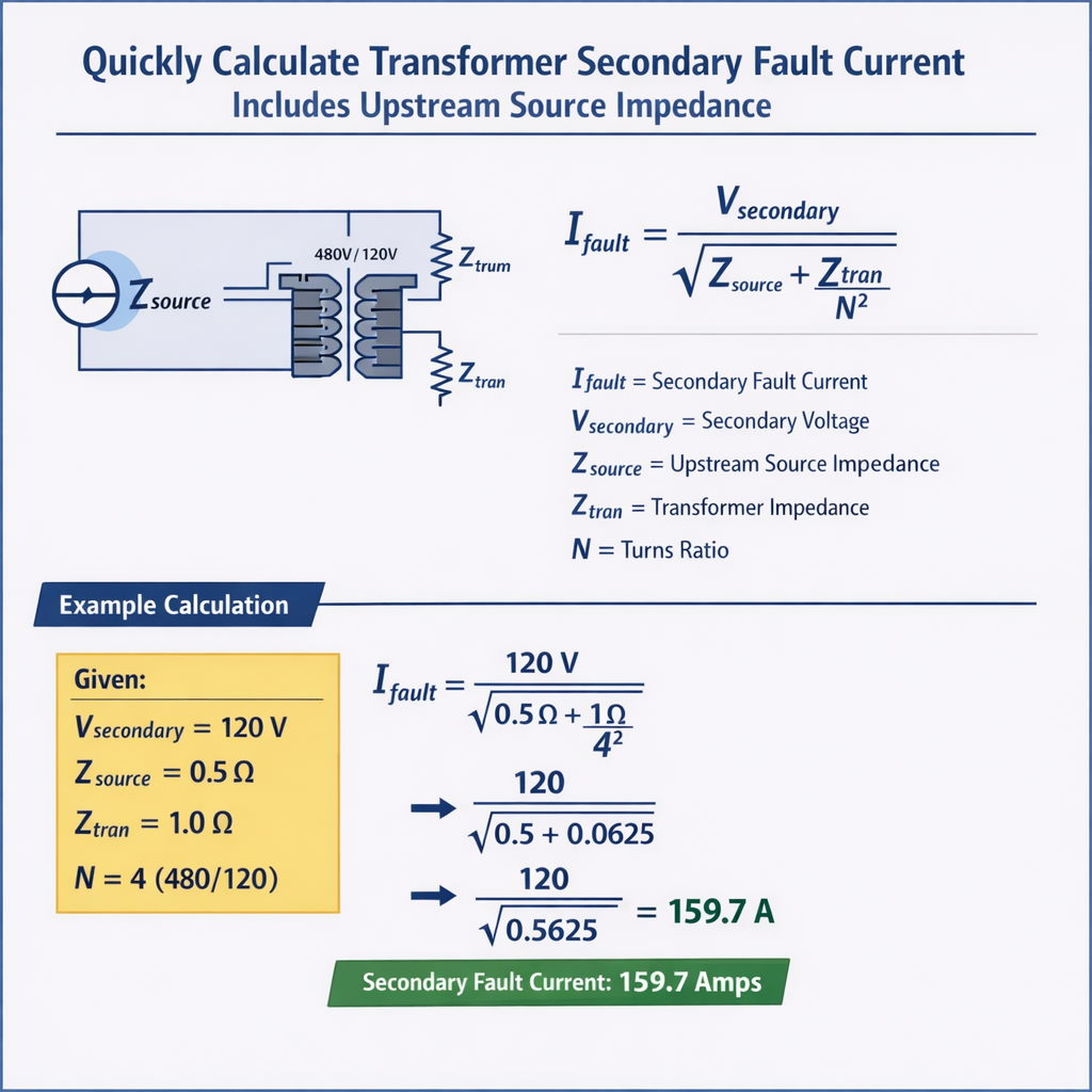
Quickly Calculate Transformer Secondary Three-Phase Fault Current (includes upstream source impedance)
Scope and practical problem statement
Engineers routinely need the available bolted three-phase and single-phase fault current at a transformer secondary while accounting for the upstream source impedance. Rapid, accurate estimation is required for protection setting, equipment short-circuit rating checks, and arc-flash studies. This article provides compact, repeatable methods (per-unit and ohmic), worked examples, typical assumptions, and cross-check tables of common transformer and network parameters.
Fundamental approach overview
Two equivalent approaches are widely used:
- Per-unit (pu) method: convert transformer and source impedances to a common MVA and voltage base, add impedances, compute pu fault current, then convert to amperes.
- Ohmic method: compute impedances in ohms referenced to the fault voltage base, sum impedances, and compute current by dividing the nominal secondary voltage by the total impedance.
Why include upstream source impedance?
The grid or local source has finite short-circuit capacity. Treating the upstream network as an "infinite bus" will overestimate fault currents and can produce incorrect settings, mis-rated equipment choices, and unsafe calculations. The upstream source is commonly characterized by a short-circuit MVA (S_sc) or an equivalent impedance (Z_source).
Essential formulas and definitions (HTML-only formulas)
Below are compact, HTML-only formulas used throughout the worked calculations. Each formula is followed by variable definitions and typical values.
Base current (three-phase):
- S_base = base power in VA (use transformer rated kVA as base).
- V_ll = line-to-line base voltage on the side where fault is evaluated (V).
- Typical: For a 500 kVA, 480 V transformer: I_base = 500000 / (1.732 * 480) ≈ 601 A.
Transformer per-unit impedance (from nameplate):
- %Z = transformer percent impedance on nameplate (%).
- Typical: small distribution transformers often 4%–6%; power transformers 8%–15%.
Source per-unit impedance referred to transformer base:
- S_sc_source = short-circuit MVA of the upstream source at the transformer's primary or point-of-common-connection (MVA).
- Note: Use the same S_base as transformer rating (MVA) when forming pu values.
- Typical: S_sc_source = 1000 MVA (strong grid), 50 MVA (weak feeder).
Total per-unit impedance seen by the fault (three-phase bolted):
- Z_feeder_pu = feeder or secondary wiring impedance expressed on the same base (optional additional impedance).
Per-unit fault current (three-phase bolted):
Fault current in amperes (three-phase):
- Combine with I_base formula above to compute amperes.
Ohmic form (direct if you have impedances in ohms):
- V_ll = nominal line-to-line voltage at fault location (V).
- Z_total_ohm = sum of transformer equivalent impedance referred to secondary (ohm) plus source impedance referred to secondary (ohm) and feeder impedance (ohm).
- When moving an impedance from primary to secondary, multiply by (V_pri / V_sec)^2.
- Example: 4800/480 V transformer has a = 4800/480 = 10, so primary ohm impedance seen on secondary is multiplied by 10^2 = 100.
Step-by-step calculation recipe (fast procedure)
- Choose a common base: use transformer nameplate kVA (S_base) and the secondary line voltage (V_secondary) for I_base.
- Compute transformer pu impedance Z_t_pu = %Z / 100.
- Obtain upstream short-circuit MVA at the transformer's primary (S_sc_source). If given at a different voltage, reflect to primary using appropriate conversions or use per-unit network simplification.
- Compute Z_source_pu = S_base / S_sc_source.
- Compute Z_total_pu = Z_t_pu + Z_source_pu + Z_feeder_pu (if included).
- Compute I_fault_pu = 1 / Z_total_pu.
- Compute I_base = S_base / (sqrt(3) * V_secondary).
- Compute I_fault = I_fault_pu * I_base.
- If required, compute asymmetrical peak using X/R and DC component formulas for protection coordination.
Accounting for generator or motor sources
When the upstream source includes synchronous machines, represent their contribution by a short-circuit MVA or the direct positive-sequence subtransient reactance X"}(double quote) "d''. Use machine Xd'' to form equivalent Z_source. Manufacturers' data or system studies provide that value.
Extensive tables of common values
| Transformer kVA | Secondary V_ll (V) | %Z typical | I_base (A) | Approx. bolted 3ϕ fault at infinite source (A) |
|---|---|---|---|---|
| 25 kVA | 480 | 4.0 | 30.1 | ~750 A |
| 50 kVA | 480 | 4.5 | 60.2 | ~1.34 kA |
| 150 kVA | 480 | 5.0 | 180.6 | ~3.6 kA |
| 500 kVA | 480 | 5.75 | 601.0 | ~10.5 kA |
| 1000 kVA | 480 | 7.0 | 1202.1 | ~17.2 kA |
| 2500 kVA | 480 | 8.5 | 3005.4 | ~35.4 kA |
| Upstream short-circuit MVA (S_sc) | Equivalent Z_source_pu for 500 kVA base | Interpretation |
|---|---|---|
| 1000 MVA | 0.0005 | Very strong utility (virtually infinite) |
| 500 MVA | 0.001 | Strong substation |
| 100 MVA | 0.005 | Medium strength feeder |
| 50 MVA | 0.01 | Weak local grid or long feeder |
| 10 MVA | 0.05 | Very weak source (e.g., small generator) |
| Typical transformer X/R ratio | Effect on DC offset decay | Protection note |
|---|---|---|
| 2.0 | Moderate X/R; DC decays faster | Less peak asymmetry, easier relay setting |
| 5.0 | High X/R; DC decays slower | May produce significant asymmetrical peak |
| 10.0 | Very high X/R; slow DC decay | Consider peak factor when selecting breakers |
Accounting for single-line-to-ground faults and delta/wye connections
For single-line-to-ground faults, consider zero-sequence network. Wye-connected neutrals with impedance and grounding transform the impedance summation. The general per-unit approach still applies but requires sequence network combination.
- For grounded wye on secondary with low impedance neutral, the single-phase fault current can be large compared with three-phase fault current depending on zero-sequence impedance.
- For delta-connected primary, zero-sequence currents are blocked from primary side; the neutral grounding method dictates zero-sequence impedance contribution.
Worked example 1 — Distribution transformer at typical utility
Problem statement: A 500 kVA, 480 V (LV) / 4800 V (HV) delta-wye transformer has %Z = 5.75% on the nameplate. The upstream utility short-circuit capacity at the transformer's primary (4800 V bus) is 500 MVA. Compute the bolted three-phase fault current available at the 480 V secondary terminals, neglecting feeder impedance.
Step-by-step solution
Step 1 — Define base and compute I_base
S_base = 500 kVA = 500000 VA. V_secondary = 480 V.
I_base = S_base / (sqrt(3) * V_secondary) = 500000 / (1.732 * 480) ≈ 601.0 A.
Step 2 — Transformer pu impedance
Z_t_pu = %Z / 100 = 5.75 / 100 = 0.0575 pu.
Step 3 — Source pu impedance
Z_source_pu = S_base / S_sc_source. Here S_sc_source = 500 MVA = 500000 kVA; S_base = 500 kVA.
Z_source_pu = 500 kVA / 500000 kVA = 0.001 pu.
Step 4 — Total pu impedance (neglect feeder):
Z_total_pu = Z_t_pu + Z_source_pu = 0.0575 + 0.001 = 0.0585 pu.
Step 5 — Per-unit fault current:
I_fault_pu = 1 / Z_total_pu = 1 / 0.0585 ≈ 17.094 pu.
Step 6 — Fault current in amperes:
I_fault = I_fault_pu * I_base = 17.094 * 601.0 ≈ 10,280 A.
Interpretation: The available bolted three-phase fault current at the 480 V secondary is approximately 10.3 kA. If the utility were treated as infinite (Z_source_pu ≈ 0), the result would be I_fault ≈ (1/0.0575)*601 ≈ 10,450 A — a small difference. For weaker sources the difference increases significantly.
Worked example 2 — Weak upstream feeder and feeder impedance included
Problem statement: Same 500 kVA transformer with %Z = 5.75% feeding a motor panel through 20 meters of 4/0 Cu conductor per phase. The upstream short-circuit at the 4800 V primary is 50 MVA (weak). Compute bolted three-phase fault at transformer secondary including feeder impedance.
Assumptions and conductor data
- 4/0 Cu single conductor approximate impedance at 75°C: R ≈ 0.000321 ohm/m, X ≈ 0.00008 ohm/m per phase (values representative; confirm from tables).
- 20 m length one-way → 40 m round-trip equivalent in series for fault (phase-to-phase the path is through two conductors but for three-phase bolted fault use phase impedance to neutral assumption; as an engineering simplification use per-phase length 20 m and include both R and X per phase).
- Feeder impedance per phase: Z_feeder_ohm ≈ (R + jX) * length = (0.000321 + j0.00008) * 20 ≈ 0.00642 + j0.0016 ohm.
- For three-phase calculation, convert feeder impedance to pu on the 480 V, 500 kVA base: Z_base_ohm = V_secondary^2 / S_base = (480^2) / 500000 = 0.4608 ohm.
Step-by-step solution
Step 1 — Compute I_base (as before): I_base = 601.0 A.
Step 2 — Z_t_pu = 0.0575 pu (from nameplate).
Z_source_pu = S_base / S_sc_source = 0.5 MVA / 50 MVA = 0.01 pu.
Step 4 — Feeder impedance in pu:
Z_base_ohm = 0.4608 ohm.
Z_feeder_ohm = 0.00642 + j0.0016 ≈ magnitude 0.0066 ohm. For bolted three-phase symmetrical calculations we can use the magnitude as added resistive/reactive contribution, but use magnitude for rough current estimate.
Z_feeder_pu ≈ Z_feeder_ohm / Z_base_ohm ≈ 0.0066 / 0.4608 ≈ 0.0143 pu.
Step 5 — Combine impedances (use magnitude summation for quick estimate; for phasor-accurate result combine complex values):
Z_total_pu ≈ Z_t_pu + Z_source_pu + Z_feeder_pu = 0.0575 + 0.01 + 0.0143 = 0.0818 pu.
Step 6 — Per-unit fault current:
I_fault_pu = 1 / Z_total_pu = 1 / 0.0818 ≈ 12.22 pu.
Step 7 — Fault current in amperes:
I_fault = I_fault_pu * I_base = 12.22 * 601.0 ≈ 7,343 A.
Interpretation: Including a weaker upstream source (50 MVA) and the feeder impedance reduces the available bolted three-phase fault current to about 7.34 kA, a ~29% reduction compared to the strong grid example. For protection coordination and breaker selection, this is a large change and must be included in calculations.
Asymmetrical peak and DC offset (practical note for protection)
Relays and breakers must withstand the asymmetrical peak current that occurs immediately after fault inception due to the DC component. Estimate the initial asymmetrical peak by multiplying initial symmetrical RMS value by a peak factor that depends on X/R of the circuit and the point-on-wave of fault initiation.
Approximate peak factor formula (worst-case instantaneous inception at voltage zero):
k_peak ≈ sqrt(2) * (1 + e^{-π/(2*(X/R))})
- Where X/R is the circuit reactance-to-resistance ratio using equivalent series values (e.g., combined source and transformer X/R).
- Use this factor times RMS symmetrical current to estimate initial peak current.
Example: For X/R = 5, e^{-π/(2*5)} ≈ e^{-0.314} ≈ 0.73. k_peak ≈ 1.4142 * (1 + 0.73) ≈ 2.45. If RMS symmetrical fault is 7.34 kA, peak could be up to ≈ 18 kA momentarily. Verify breaker peak withstand capability and peak let-through (Ipk).
Practical tips, approximations and pitfalls
- Use transformer %Z on nameplate and transformer rating as S_base to avoid conversion mistakes.
- Always ensure S_sc_source is specified at the same point and voltage as the transformer primary. If not, transform the S_sc to the appropriate base.
- For multi-transformer banks or parallel transformers, perform network reduction and add per-unit impedances appropriately.
- Zero-sequence network is required for single-line-to-ground faults — do not use three-phase formulas for ground faults unless the neutral is solidly grounded and zero-sequence impedances are negligible.
- Small feeder impedances at low voltage can be significant relative to transformer impedance—include them when distance or conductor sizes are substantial.
- When source is very strong (S_sc >> S_base) Z_source_pu -> 0 and the transformer dominates. When source is weak (S_sc comparable to S_base) the source contribution must be included.
Additional worked analysis — Example 3: Reflecting upstream generator impedance
Problem statement: A 150 kVA pad-mounted transformer, 480 V LV, 4800 V HV, %Z = 4.5%. Upstream is a 1.0 MVA standby generator at 4800 V with Xd'' = 0.15 pu on its own MVA base. Compute three-phase fault at 480 V secondary including generator contribution. Neglect feeder impedance.
Solution outline
Step 1 — Set S_base = 150 kVA and compute I_base: I_base = 150000 / (1.732 * 480) ≈ 180.6 A.
Step 2 — Transformer Z_t_pu = 0.045 pu.
Step 3 — Convert generator subtransient reactance to S_base: Given Xd''_gen = 0.15 pu on 1 MVA base. To refer to S_base = 0.15 MVA, use:
Z_gen_pu_on_Sbase = Xd''_gen * (S_gen / S_base) = 0.15 * (1000 kVA / 150 kVA) = 0.15 * 6.6667 = 1.0 pu.
Interpretation: On the 150 kVA base the generator looks very weak (high impedance) relative to the small transformer.
Step 4 — Z_total_pu = Z_t_pu + Z_gen_pu = 0.045 + 1.0 = 1.045 pu.
Step 5 — I_fault_pu = 1 / 1.045 = 0.957.
Step 6 — I_fault = 0.957 * 180.6 ≈ 173 A.
Interpretation: The available fault current is actually slightly less than transformer rated current because the generator is relatively small. This highlights the importance of converting machine reactances to the selected pu base before summing.
Normative references and further reading
- IEEE Std C37.010 — "Application Guide for AC Generator Protection" (generator short-circuit and subtransient reactance guidance). Available from IEEE: https://standards.ieee.org
- IEEE Std 141 (Green Book) — "Grounding of Industrial and Commercial Power Systems" (system grounding, sequences). https://standards.ieee.org
- IEC 60909 — "Short-circuit current calculations in three-phase AC systems" provides international methods for fault current calculation including correction factors. See IEC official site: https://www.iec.ch
- NEMA and ANSI transformer standards for nameplate impedance interpretation: https://www.nema.org
- IEEE Std C37.010 and ANSI/IEEE C37 series for breaker performance and let-through ratings: https://standards.ieee.org
Checklist for practical engineering application
- Obtain accurate transformer nameplate data: S_rated, V_primary, V_secondary, %Z, X/R if available.
- Obtain upstream short-circuit MVA or equivalent impedance at the correct bus and voltage.
- Decide base values consistently (use transformer rating as S_base for LV fault calculations).
- Include feeder and other series impedances by converting to the chosen base or to ohms referenced to the same voltage.
- Compute per-unit totals, convert to amperes, and then apply asymmetry/peak factors if required for breaker selection.
- Document assumptions and worst-case points on the waveform where DC offset is maximum.
Summary of quick reference formula set
For a fast spreadsheet or calculator, implement the following sequence:
- Input: S_base (kVA), V_secondary (V), %Z_transformer (%), S_sc_source (MVA), Z_feeder_ohm (optional).
- Compute: I_base = S_base / (sqrt(3) * V_secondary).
- Compute: Z_t_pu = %Z_transformer / 100.
- Compute: Z_source_pu = S_base / S_sc_source (ensure units consistent: kVA/MVA).
- Compute: Z_feeder_pu = Z_feeder_ohm / (V_secondary^2 / S_base) if including feeder ohmic impedance.
- Compute: Z_total_pu = Z_t_pu + Z_source_pu + Z_feeder_pu.
- Compute: I_fault = I_base / Z_total_pu.
Quick calculation sanity checks
- If Z_source_pu << Z_t_pu, source is strong and transformer dominates.
- If Z_source_pu ≈ Z_t_pu, both must be accounted for carefully.
- Ensure that computed I_fault does not exceed interrupting rating of protective devices and equipment thermal ratings.
Final engineering considerations
Always cross-validate quick per-unit calculations with a specialized short-circuit software tool or system study for complex networks, paralleled transformers, or low X/R cases where asymmetry matters. Document the base choices and conversion steps to ensure results are reproducible and auditable.
For additional authority and detailed procedures consult IEC 60909 for international calculation standards and the relevant IEEE/ANSI curve and device standards for protective equipment coordination.