This article explains NEC grounding and bonding calculations for separately derived generator systems accurately safely.
Quick NEC 250 30 250 34 calculator methodology ensures compliance, conductor sizing, and impedance control.
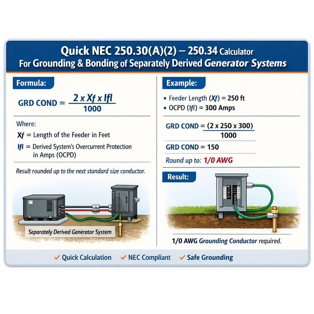
Quick NEC 250.30 / 250.34 Grounding & Bonding Calculator for Separately Derived Generator Systems
Overview of NEC 250.30 and 250.34 requirements for separately derived generator systems
NEC Article 250.30 establishes grounding and bonding requirements for separately derived systems, including generator frames, neutral bonding, grounding electrode conductors (GECs), and connections to the grounding electrode system. Article 250.34 addresses additional requirements where neutral bonding, grounding electrodes, and grounding electrode conductor sizing intersect with service and feeder arrangements for separately derived systems.
Key objectives of a quick calculator tool
- Determine whether the generator is a separately derived system and if neutral-to-ground bonding is required at the generator source.
- Size grounding electrode conductors (GEC) and equipment grounding conductors (EGC) to meet NEC thermal and mechanical requirements.
- Estimate ground-fault currents, impedance, and minimum conductor cross-sections using adiabatic short-circuit methods.
- Provide conservative design checks for electrode resistance and bonding jumpers for safety and system performance.
Fundamental concepts and variables used in calculations
Use these definitions consistently in every calculation and example to ensure clarity and traceability.
- VLL — Line-to-line system voltage (volts). Typical values: 480, 4160, 208, 240.
- Vph — Line-to-neutral (phase) voltage (volts). For wye: Vph = VLL / sqrt(3).
- Zs — Total ground-fault loop impedance (ohms) seen by a fault current path.
- Ig — Available ground-fault current at the point of fault (amperes): Ig = Vph / Zs.
- S — Minimum conductor cross-sectional area (mm2 or circular mils); when using adiabatic equation, S units depend on k constant units.
- t — Fault clearing time (seconds): fuse or breaker clearing time for the protective device that limits fault duration.
- k — Adiabatic constant for conductor material and initial/final temperatures (typical k copper ≈ 115, aluminium ≈ 148; check manufacturer and code tables).
Core formulas
All formulas are shown as plain arithmetic expressions using standard characters.
Available ground-fault current (single-phase to ground):
Where:
- V_ph = V_LL / sqrt(3)
- Z_s = Z_generator + Z_ground_path + Z_system (ohms)
Adiabatic conductor sizing formula (short-circuit thermal withstand):
Where:
- S = required conductor cross-sectional area
- I_k = prospective short-circuit current (amperes) for the conductor being protected or bonded
- t = fault duration in seconds (s)
- k = material constant (typical copper k ≈ 115; typical aluminium k ≈ 148)
Ohm's law for impedance path:
Resistance of ground rod approximation (for a single rod, empirical):
R_rod ≈ ρ / (2 * π * L) * (ln(4 * L / d) - 1)
Where:
- ρ = soil resistivity (ohm-meters), typical values: 100–1000 Ω·m
- L = rod length (m)
- d = rod diameter (m)
Algorithm for a Quick NEC 250.30 / 250.34 grounding-bonding calculator
- Identify system parameters: generator kVA, VLL, connection type (wye/delta), grounding method (solid, high-resistance, impedance), and whether the generator is separately derived (neutral isolated from supply neutral).
- Calculate phase voltage: V_ph = V_LL / sqrt(3).
- Estimate internal generator subtransient reactance and source impedance (use manufacturer data or standard per unit values). Convert to Z_gen (ohms) at operating voltage.
- Estimate grounding path impedance (Z_ground) — include grounding electrode(s), conductor lengths and EGC/resistance to ground. Use electrode empirical formulas and tabled conductor impedance per length.
- Compute Z_s = Z_gen + Z_ground and evaluate Ig = V_ph / |Z_s|.
- Select protective device and fault clearing time t (seconds). Use device time-current curves or specified clearing times.
- Calculate required bonding / GEC conductor cross-section using S = I_g * sqrt(t) / k or size per NEC tables (250.66 for GEC, 250.122 for EGC). For compliance, pick the larger of adiabatic result and NEC table minimums.
- Report conductor size, electrode resistance goals, and any mitigation (additional rods, parallel electrodes, low-impedance connections) needed to meet step and touch voltages and code requirements.
Reference tables and typical values (illustrative)
| Generator Rated Current (A) | Typical GEC Minimum (Copper) — illustrative | Typical EGC Minimum (Copper) — illustrative | Typical Protective Device |
|---|---|---|---|
| 50 A | 8 AWG | 10 AWG | 60 A breaker/fuse |
| 100 A | 6 AWG | 8 AWG | 100 A breaker/fuse |
| 200 A | 4 AWG | 6 AWG | 225 A breaker/fuse |
| 400 A | 2 AWG | 4 AWG | 400 A breaker/fuse |
| 800 A | 250 kcmil | 3/0 AWG | 800 A breaker/fuse |
Note: The table above is illustrative and intended to show common, conservative conductor sizes used in practice. Always verify required sizing with the applicable NEC table (250.66 for GEC, 250.122 for EGC) and manufacturer data.
| Soil Resistivity (Ω·m) | Single 8 ft (2.44 m) Ground Rod Typical Resistance (Ω) | Two Rods (spaced > rod length) Estimated Resistance (Ω) |
|---|---|---|
| 50 | 6–10 | 3–6 |
| 100 | 10–20 | 5–10 |
| 250 | 20–40 | 10–20 |
| 500 | 30–70 | 15–35 |
Practical note: achieving < 25 Ω for a single rod is common in moist soils; in dry resistive soils designers commonly use multiple rods, ground rings, chemically enhanced electrodes, or ground mats.
Detailed formula walkthrough and variable explanations with typical values
Compute available ground-fault current
Step-by-step:
- Calculate V_ph = V_LL / sqrt(3). Example: for 480Y/277 V, V_ph = 480 / 1.732 ≈ 277 V.
- Estimate generator subtransient reactance Xd'' in ohms: Xd'' (pu) * (V_LL^2 / S_base). Use nameplate MVA to convert per-unit to ohms. If manufacturer data is not available, conservative assumptions must be used.
- Sum resistive and reactive terms in the fault loop to obtain |Z_s|.
- Compute Ig = V_ph / |Z_s|.
Adiabatic sizing example variables
- I_k — Use Ig or prospective fault current seen by the conductor. Typical range: 5 kA to 50 kA depending on system.
- t — Typical clearing times: instantaneous breakers (<0.02 s), thermal-magnetic breakers (0.1 s to 1.0 s), fuses variable. Use the actual protective device time-current characteristics.
- k — Use manufacturer or code table value for conductor insulation and material. Common conservative k for copper: 115.
Real-world Example 1 — 250 kVA 480Y/277 V generator separately derived, solidly grounded
Assumptions (stated): The generator is 250 kVA, 480Y/277 V, rated line current approximately 300 A, separately derived (neutral isolated from upstream). Manufacturer reports subtransient reactance Xd'' = 0.20 pu on generator base. Protective device is an upstream 400 A instantaneous-trip breaker with worst-case clearing time t = 0.05 s for a severe fault.
Step A — Compute phase voltage and base impedance
V_LL = 480 V → V_ph = 480 / 1.732 = 277 V.
Generator rated S = 250 kVA → S_base = 250 kVA. Base impedance Z_base = V_LL^2 / S_base = (480^2) / 250000 ≈ 0.9216 Ω.
Step B — Convert Xd'' to ohms
Xd'' (ohms) = Xd''(pu) * Z_base = 0.20 * 0.9216 ≈ 0.1843 Ω.
Step C — Estimate ground path resistance
Assume grounding electrode system and conductor path adds a conservative R_ground ≈ 0.5 Ω and reactance negligible for the short run. So Z_s ≈ 0.1843 + 0.5 = 0.6843 Ω (magnitude for this simplified calculation).
Step D — Compute available ground-fault current
I_g = V_ph / Z_s = 277 V / 0.6843 Ω ≈ 405 A.
Step E — Adiabatic sizing of bonding conductor
Use I_k = 405 A, t = 0.05 s, k (copper) = 115.
S = I_k * sqrt(t) / k = 405 * sqrt(0.05) / 115.
Compute sqrt(0.05) ≈ 0.22361 → numerator ≈ 405 * 0.22361 ≈ 90.5 → S ≈ 90.5 / 115 ≈ 0.787 mm2.
Interpretation: S ≈ 0.787 mm2 (≈ 18 AWG). However, NEC minimums and mechanical considerations apply. NEC Table 250.66 and 250.122 will specify larger minimum sizes. For a generator rated ~300 A, practical minimum GEC is commonly 4 AWG or larger; EGC per 250.122 for 400 A OCP is 4 AWG copper. Therefore the calculator must choose the larger of the adiabatic result and NEC table minimums — in this example a 4 AWG copper bonding conductor is selected for conservative, code-compliant design.
Summary of Example 1 decisions
- Computed available ground-fault current ≈ 405 A.
- Adiabatic sizing gave a small cross-section due to short duration and low available current, but code minimums govern selection.
- Selected bonding/GEC size: 4 AWG copper (conservative per NEC table references and mechanical robustness).
- If electrodes produce higher resistance, increase conductor cross-section only if required by fault current and protection time.
Real-world Example 2 — 1500 kVA 4.16 kV generator, separately derived with impedance grounding
Assumptions: Generator 1500 kVA at 4.16 kV, wye, neutral grounded through an impedance (limiting ground-fault current). The neutral impedance sets a maximum ground-fault current of 400 A RMS. Grounding electrode system must still be connected per NEC 250.30(A)(1). Protective device clearing: breaker clears ground faults in t = 1.0 s for phased detection and lockout. Use copper conductors and k = 115.
Step A — Phase voltage
V_ph = 4160 / 1.732 ≈ 2401 V.
Step B — Ground-fault current as limited by neutral resistor
Ig is limited to 400 A by the neutral resistor (given). For conservative checks use I_k = 400 A.
Step C — Adiabatic conductor sizing for bonding jumper between neutral and grounding electrode conductor (if a bonding jumper is required)
t = 1.0 s, I_k = 400 A, k = 115 → S = 400 * sqrt(1.0) / 115 ≈ 3.478 mm2.
Equivalent AWG: 3.478 mm2 ≈ 12 AWG. Again, NEC minimums apply and equipment grounding conductors for high-voltage/generator systems are typically much larger for mechanical strength and low impedance. Select a 2 AWG or 1/0 depending on Table 250.66 mapping and site practices. For 4.16 kV systems, parallel conductors, copper buswork, or welded connections to the electrode system are commonly used.
Step D — Grounding electrode resistance
Assume soil ρ = 200 Ω·m and using multiple 8 ft rods spaced at least 8 ft with a ring conductor, designer shall aim for <25 Ω for practical safety; however final design must evaluate step/touch potential per IEEE 80. If single rods produce R ≈ 25–40 Ω, add rods or ground ring until R < target.
Summary of Example 2 decisions
- Although adiabatic calculation suggests a small conductor, NEC and practical engineering require much larger conductors and robust bonding for high-voltage generator installations.
- Because the neutral is impedance-limited to 400 A, thermal requirements are modest, but maintenance, mechanical strength, and fault distribution require oversized conductors or bus connections.
- Connect GEC to grounding electrode system per NEC 250.30, and ensure the grounding electrode conductor is routed and protected per NEC rules.
Practical design checks and mitigations
- Always apply NEC Table 250.66 (GEC) and Table 250.122 (EGC) as baseline minimums — adiabatic calculations may produce smaller theoretical areas but code minimums prevail.
- Verify protective device actual time-current characteristics to obtain accurate t for adiabatic calculations.
- Include conductor routing, mechanical protection, and corrosion-resistant connections in final design.
- For soil resistive sites, design ground electrode arrays (multiple rods, ground rings, mats) and consider chemical electrodes or backfilled electrodes to reduce resistance.
- Document manufacturer generator impedance data; avoid assumptions when possible — use nameplate or vendor fault current curves.
Implementation notes for a Quick NEC 250.30 / 250.34 calculator
- Inputs required:
- Generator kVA and voltage (VLL)
- Connection type (wye/delta), separately derived flag
- Manufacturer short-circuit impedance (Xd'') or conservative assumed value
- Ground electrode configuration and soil resistivity
- Protective device type and clearing time or characteristic curve
- Desired units for outputs (AWG, kcmil, mm2)
- Calculate per the algorithm above and cross-check both adiabatic sizing and NEC table minimums.
- Output should provide:
- Prospective ground-fault current at generator terminals
- Minimum GEC and EGC sizes and recommended sizes per NEC table
- Estimated grounding electrode resistance and mitigation steps
- Clear engineering disclaimers requiring final verification per NEC and manufacturer data
Standards, code references, and further reading
- NFPA 70, National Electrical Code (NEC), Article 250 — Grounding and Bonding. See the current edition at the National Fire Protection Association: https://www.nfpa.org/
- NEC 250.30 — Grounding separately derived systems (refer to the local copy of NEC for precise requirements and table references).
- NEC 250.34 — Additional grounding electrode system requirements where separately derived systems are involved.
- NEC Table 250.66 — Size of grounding electrode conductor for grounding electrode conductor connected to service equipment, disconnecting means, or a separately derived system.
- NEC Table 250.122 — Equipment grounding conductor requirements for specific overcurrent device ratings.
- IEEE Std 142 (Green Book) — Grounding of industrial and commercial power systems, for analysis of grounding, step and touch potentials, and electrode design guidance: https://standards.ieee.org/
- IEEE Std 80 — Guide for safety in AC substation grounding for step and touch potential methods: https://standards.ieee.org/
- Manufacturer generator short-circuit data and transient impedance specifications — consult OEM datasheets for accurate Z values.
Best practices and compliance checklist
- Confirm whether the generator is a separately derived system — isolated neutral means neutral-to-ground bond is made at the generator or derived-transformer location per NEC 250.30.
- Make connections to the grounding electrode system at the generator per NEC 250.30(A)(1) and ensure mechanical protection of GECs.
- Size conductors using the larger of adiabatic calculation and the NEC table minimums. Document assumptions and calculations.
- Mitigate high electrode resistance with additional rods, rings, or enhanced electrodes; verify step and touch voltages when personnel exposure is possible.
- Provide clear labeling and diagrams of neutral-to-ground bond locations for maintenance and inspection.
- Retain manufacturer fault data and protective device curves for future troubleshooting and verification.
Closing notes on engineering judgment and legal compliance
The arithmetic methods shown are deterministic engineering calculations that must be supplemented with the current NEC edition text, manufacturer-provided impedance data, and site-specific soil testing. Always confirm final conductor sizes and electrode designs with the Authority Having Jurisdiction (AHJ) and ensure that the selected solution meets both safety performance and regulatory requirements. For authoritative code interpretation consult NFPA resources and local code officials.
Useful external resources
- NFPA — National Fire Protection Association: https://www.nfpa.org/
- IEEE Standards — search for IEEE Std 142 and IEEE Std 80: https://standards.ieee.org/
- OSHA electrical safety guidelines (for workplace electrical grounding considerations): https://www.osha.gov/
- Manufacturer generator technical literature — consult OEM sites such as Caterpillar, Cummins, Kohler for generator transient impedance data and installation guides.