This article provides precise methods for calculating 277 480 V wye service feeder sizing accurately.
It integrates mixed load diversity, harmonics, voltage drop, and code compliance for instant results calculations.Instant Feeder Ampacity & Conductor Suggestion for 277/480 V Wye Mixed Loads
Scope and applicability for 277 480 V wye service feeder sizing calculator
This document defines the technical rationale, formulas, and example workflows for an instant online 277/480 V Wye service feeder sizing calculator intended for engineers, designers, and electrical estimators. The focus is on mixed-load service feeders: lighting and general-purpose loads on 277 V (line-to-neutral), three-phase loads on 480 V (line-to-line), motors with variable torque, and non-linear loads driving harmonics.
System fundamentals and key electrical relationships
Three-phase power basics
For balanced three-phase loads on 480 V line-to-line systems the core conversion is:
Where:
- I = line current (A)
- S = apparent power (kVA)
- V = line-to-line voltage (V), typical 480 V
- √3 = 1.732051 (square root of 3)
Typical value example: For a 100 kVA transformer on 480 V three-phase: I = 100 × 1000 / (1.732 × 480) ≈ 120.3 A.
Single-phase (line-to-neutral) loads on 277 V
For single-phase loads connected line-to-neutral at 277 V (lighting, some small loads):
Where:
- I = current (A)
- P = real power (kW)
- V = phase voltage (V), typical 277 V
- PF = power factor (unitless; typical lighting PF = 0.9 to 1.0)
Typical value example: 10 kW of LED lighting at PF = 0.9 → I ≈ 10×1000/(277×0.9) ≈ 40.11 A.
Continuous loads, demand factors and NEC constraints
NEC fundamentals used in calculator logic:
- Continuous loads (≥3 hours): multiply by 125% for conductor ampacity and overcurrent device sizing (NEC 210.19(A)(1), 215.2(A)(1), 240.6(A)).
- Aggregate feeders with mixed general and continuous loads: apply applicable demand factors per NEC Article 220 when sizing feeders.
- Adjust conductor ampacity for ambient temperature, number of current-carrying conductors, and conductor bundling per NEC 310.15 tables.
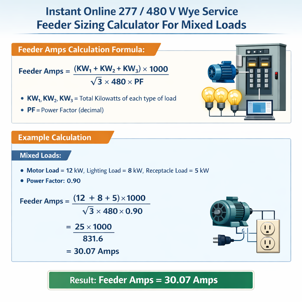
Formulas used by the calculator
All formulas are expressed in plain HTML-friendly notation. Each formula is followed by variable definitions and typical values.
Three-phase current from kVA
- S = apparent power in kVA (typical values: 5, 10, 25, 50, 100, 200, 500)
- V = line-to-line voltage (480 V for this calculator)
- √3 = 1.732051
Single-phase current from kW (277 V)
- P = real power in kW (typical lighting circuits: 1–50 kW)
- V = 277 V
- PF = power factor (typical LED lighting PF = 0.9; resistive loads PF = 1.0)
Aggregate feeder current for mixed 277/480 loads
Compute currents separately for 480 V three-phase loads (I480) and 277 V single-phase loads (I277). Convert single-phase currents into equivalent three-phase contribution at service feeder, if required, by converting P to kVA at the system basis and summing apparent powers:
- S_480 = sum of three-phase kVA loads
- S_277_total = sum of single-phase loads' kVA referenced to the three-phase source (kW/PF)
- V = 480 V
Voltage drop for three-phase feeders
Recommended formula for voltage drop (line-to-line) for a balanced three-phase feeder:
- Vdrop = voltage drop in volts
- I = load current in A
- R = conductor resistance per unit length (Ω per unit length)
- X = conductor reactance per unit length (Ω per unit length)
- cosφ = power factor; sinφ = √(1 − cos²φ)
- L = one-way conductor length (same distance from service to load)
Typical guideline: design for ≤3% voltage drop at end loads for feeders + branch circuits combined (industry guideline).
Conductor ampacity adjustment factors
Calculator applies derating factors:
- Ambient temperature correction per NEC 310.15(B)(2)(a) (e.g., 30 °C, 40 °C, 50 °C with lookup multipliers).
- More than three current-carrying conductors in a raceway: adjustment per NEC 310.15(B)(3)(a).
- Continuous loads: 125% multiplier.
Common conversion and lookup tables
Below are practical tables frequently used in instant calculators: kVA-to-current conversion at 480 V three-phase and single-phase currents for typical lighting loads at 277 V.
| Three-phase Transformer kVA | Formula | Line Current @ 480 V (A) |
|---|---|---|
| 5 kVA | I = 5×1000/(1.732×480) | 6.02 A |
| 10 kVA | I = 10×1000/(1.732×480) | 12.03 A |
| 15 kVA | I = 15×1000/(1.732×480) | 18.05 A |
| 25 kVA | I = 25×1000/(1.732×480) | 30.08 A |
| 50 kVA | I = 50×1000/(1.732×480) | 60.15 A |
| 75 kVA | I = 75×1000/(1.732×480) | 90.23 A |
| 100 kVA | I = 100×1000/(1.732×480) | 120.30 A |
| 200 kVA | I = 200×1000/(1.732×480) | 240.60 A |
| 500 kVA | I = 500×1000/(1.732×480) | 601.50 A |
| Lighting Load (kW) | Assumed PF | Current @ 277 V (A) |
|---|---|---|
| 1 kW | 0.90 | 4.01 A |
| 5 kW | 0.90 | 20.06 A |
| 10 kW | 0.90 | 40.11 A |
| 20 kW | 0.90 | 80.22 A |
| 50 kW | 0.90 | 200.55 A |
| 100 kW | 0.90 | 401.09 A |
Sizing workflow implemented in an instant online calculator
The calculator implements a deterministic sequence to ensure compliance and to return results in under a second. Key steps:
- Input collection: list loads by type (kW/kVA), connection (277 V single-phase or 480 V three-phase), duty (continuous or non-continuous), PF, and load location distances.
- Convert all loads to apparent power (kVA). For single-phase loads: S = P / PF.
- Apply demand factors per NEC Article 220 where applicable (lighting, receptacles, HVAC diversity), and perform aggregation.
- Compute preliminary feeder current: I = S_total×1000/(√3×480).
- Apply continuous load multiplier (125%) if any portion is continuous and requires conductor ampacity sizing.
- Apply conductor adjustment factors: ambient temperature, bundling, and correction for insulation rating (60 °C, 75 °C, 90 °C column selection).
- Select conductor size with ampacity ≥ adjusted ampacity requirement using a conductor ampacity database.
- Select OCPD: per NEC choose the next standard breaker rating, ensuring not to exceed conductor ampacity; use rounding rules in NEC 240.6(A).
- Evaluate voltage drop using length, R and X values for chosen conductor; iterate conductor size if voltage drop > 3%.
- Harmonics: estimate neutral currents for non-linear loads and oversize neutral if K-factor or IEEE 519 requirements indicate.
Adjustment examples and rules embedded
- Ambient temperature correction example: THHN copper at 75 °C base ampacity × temperature factor from NEC table to compute corrected ampacity.
- More than three current-carrying conductors: apply 80% factor for 4–6 conductors, etc., per NEC 310.15(B)(3)(a).
- Motor starting contribution: the calculator flags short-time inrush and suggests evaluation for transient voltage drop, but sizes feeders based on motor full-load current and NEC motor rules (Article 430).
Harmonics, neutral sizing and power quality considerations
Non-linear loads such as VFDs, UPS systems, and computers produce triplen harmonics that add in the neutral on 3-phase 4-wire Y systems. Key calculator capabilities:
- Estimate neutral current using harmonic distortion factors or measured THD(I) if provided.
- Apply IEEE 519 recommended limits for point-of-common coupling (PCC) harmonic distortion; provide warnings when large non-linear load fractions exist.
- Neutral sizing: if K-factor or computed neutral current > phase conductor rating, recommend neutral upsizing or use of 4-pole isolation transformers.
Real-world worked examples
Example 1 — Small commercial building mixed loads (lighting + HVAC + receptacles)
Project synopsis: A small commercial service with the following loads connected to a 480Y/277 V system:
- Lighting: 25 kW (277 V single-phase), PF = 0.90, continuous
- HVAC: three-phase packaged unit loads aggregated to 75 kVA (480 V three-phase), non-continuous
- General receptacles and small equipment: 15 kW (277 V single-phase), PF = 0.95, non-continuous
- Feeder length to the farthest load: 60 meters (one-way)
Lighting is continuous (25 kW). NEC requires sizing conductors for continuous portions at 125%.
Adjusted continuous requirement: 33.4 × 1.25 = 41.8 A additional margin to feeder ampacity.
Step 6 — Combine and apply continuous factor properly:Method A (compliant): Increase the computed feeder current to include continuous load multiplier on continuous portion before selecting conductor.
Choose a conductor ampacity ≥ 150.9 A after applying ambient and grouping adjustments. Typical copper conductor options (example): 3/0 AWG copper THHN at 75 °C has ampacity ≈ 200 A (nominal). Therefore 3/0 AWG copper acceptable before adjustment.
Select breaker > 150.9 A standard size: 175 A or 200 A. NEC rounding rules often select next standard rating (e.g., 175 A then 200 A). Verify that the chosen breaker does not exceed conductor ampacity.
Step 8 — Voltage drop check:Assume conductor resistance/reactance yields voltage drop at 150.9 A over 60 m. Use conductor R and X and formula Vdrop = √3 × I × (R cosφ + X sinφ) × L. If computed Vdrop exceeds 3% of 480 V (14.4 V per phase) then increase conductor size.
Result summary:- Computed feeder design current (with continuous adjustment): 150.9 A
- Recommended conductor: 3/0 AWG copper (example choice; verify ampacity table and local code)
- Recommended OCPD: standard 175 A or 200 A depending on coordination and breaker availability
- Voltage drop and ambient correction must be verified with conductor R/X tables and site conditions
Example 2 — Light industrial plant with VFDs and high harmonic content
Project synopsis: A light industrial facility with:
- Six 30 HP three-phase induction motors driven by VFDs (480 V) — total motor rating 180 HP
- Process heaters and lighting: combined 40 kW (277 V), lighting continuous, heaters non-continuous
- UPS and IT loads: 30 kW (277 V) with significant non-linear current (THD(I) estimated 30%)
- Feeder length: 120 meters one-way
Use NEMA FLC (approximate) for 480 V motors. Typical 30 HP motor FLC at 480 V ≈ 36 A each (approximate; verify with manufacturer)
Assume motor PF ≈ 0.85. Each motor kW = 30 HP × 0.746 = 22.38 kW; kVA per motor = 22.38/0.85 ≈ 26.33 kVA
S_total_adj = motor kVA + (lighting kVA × 1.25) + UPS kVA = 157.98 + (44.44 × 1.25) + 31.58 = 157.98 + 55.55 + 31.58 = 245.11 kVA
Large fraction of non-linear loads (VFDs and UPS) produce triplen harmonics. For 6 VFD-driven motors, each VFD can produce significant 3rd, 9th harmonics which add in neutral.
Estimate neutral current and possible oversizing: IEEE 519 and manufacturers recommend either oversizing the neutral conductor or using 3-phase isolation transformers or dV/dt filters and multi-pulse VFDs to reduce harmonic generation.
Step 7 — Conductor selection and voltage drop:Assuming required ampacity ≈ 294.5 A, select conductor 4/0 AWG copper at 75 °C with ampacity ≈ 230–260 A — this is insufficient. Next size: 250 kcmil copper approx ampacity ~310 A (verify ampacity table). Select 250 kcmil copper if ambient and bundling corrections allow.
Step 8 — OCPD selection:Select protective device rated for motor starting and inrush; feeder OCPD must be consistent with conductor ampacity: choose standard breaker size 300 A if conductor ampacity ≥ 300 A. Use NEC rules for branch-circuit motor protection (Article 430) for motor short-time and overload protection.
Step 9 — Voltage drop:Given the 120 m feeder length and heavy currents, compute Vdrop and evaluate if larger conductor is required to meet ≤3% target. If not achieved, consider parallel runs or step-up transformer closer to load.
Result summary:- Calculated feeder design current (after continuous adjustment): ≈ 294.5 A
- Recommended conductor: 250 kcmil copper (subject to ampacity verification and ambient correction)
- Neutral: consider oversizing or harmonic mitigation per IEEE 519 recommendations
- OCPD: select appropriate standard rating (e.g., 300 A) while ensuring conductor protection compliance
Regulatory references and authoritative resources
Key normative references used in the sizing methodology and embedded in the calculator logic:
- NFPA 70, National Electrical Code (NEC) — for conductor ampacity, overcurrent protection, and feeder sizing rules. See https://www.nfpa.org/nec
- IEEE Std 519 — Recommended Practice and Requirements for Harmonic Control in Electrical Power Systems (harmonic limits and assessment). See https://ieeexplore.ieee.org/document/8258900 (or IEEE Xplore)
- IEC 60364 — Electrical installations of buildings (internationally recognized guidance). See https://www.iec.ch
- NEMA and UL standards for cable insulation, motor ratings, and VFD characteristics. See https://www.nema.org and https://www.ul.com
- NEC tables referenced for ampacity and correction factors: NEC Article 310 and Table references (local edition and year may apply).
Implementation considerations for an instant online calculator
Practical engineering and UX choices for a high-accuracy instantaneous feeder sizing tool:
- Pre-cached ampacity and conductor R/X tables for common insulation types and sizes for rapid lookup.
- Interactive inputs for load types, PF, diversity/demand selections (with presets for lighting, receptacles, motors, HVAC).
- Automated continuous-load detection and automatic application of the 125% rule where applicable.
- Built-in voltage-drop calculator with editable R and X values by conductor type and length for run-time validation.
- Harmonic impact estimator (based on percent non-linear load and THD inputs) with neutral up-sizing recommendations and mitigation notes referencing IEEE 519.
- Produce printable design summary with conductor sizes, OCPD suggestions, voltage drop, and code references for documentation.
Best practices and engineering checks
- Always compare computed currents to manufacturer motor full-load current (FLC) tables rather than relying solely on horsepower conversions.
- Validate power factor assumptions; for VFD-fed motors and UPS, use measured PF when available.
- Perform coordination and selective protection studies for feeders with multiple branches and motor starting coordination.
- For installations with significant harmonics, perform harmonic studies and consider multi-pulse VFDs, active harmonic filters, or isolation transformers.
- Check local amendments to the NEC or relevant national codes (IEC variants) before finalizing conductor and protective device selection.
Summary of actionable outputs from the calculator
An instant online 277/480 V Wye service feeder sizing calculator should present clear engineering outputs that include:
- Total feeder apparent power (kVA) and computed phase current (A)
- Separate contributions from 277 V single-phase and 480 V three-phase loads
- Adjusted feeder current accounting for continuous loads and code-based demand factors
- Recommended conductor size(s) with applicable ampacity and correction factors applied
- Recommended overcurrent protective device rating with notes on NEC rounding rules
- Voltage drop calculation and flag if above recommended threshold
- Harmonic impact summary and neutral sizing recommendation where applicable
- References to NEC articles, IEEE 519, and other standards used for the calculation
Further reading and authoritative links
- NFPA 70 National Electrical Code — official information and code purchase: https://www.nfpa.org/nec
- IEEE Std 519 — Harmonic control recommendations: https://standards.ieee.org/standard/519-2014.html
- IEC 60364 series — International electrical installation standards: https://www.iec.ch/standards
- NEMA applications guides for motors and drives: https://www.nema.org/Standards
- Manufacturer resources for motor FLC and VFD harmonic performance (Siemens, ABB, Schneider Electric, Eaton).
Use this technical methodology as the backbone of an instant online 277/480 V Wye service feeder sizing calculator to produce code-compliant, practical, and verifiable conductor and protection selections. Always verify final designs against the latest code edition and field-specific details, and perform detailed coordination and harmonic studies where loads are complex.