This article explains an instant kW to kVAr conversion tool for engineers and technicians worldwide.
It covers power triangle, power factor, formulas, examples, normative references, and practical calculation steps guidance.
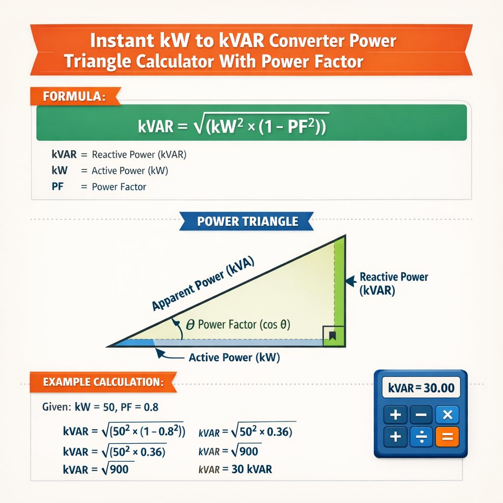
Instant kW to kVAr Converter and Power Triangle Calculator with Power Factor
Power triangle fundamentals and core equations
The power triangle graphically represents real power (P), reactive power (Q), and apparent power (S). Real power P (kW) performs useful work or delivers heat; reactive power Q (kVAr) sustains electric and magnetic fields in inductive and capacitive loads; apparent power S (kVA) is the vector sum of P and Q and represents the current-producing capability of the system. Power factor (PF) is the cosine of the phase angle φ between voltage and current and is the ratio of P to S. Key algebraic relations (displayed using plain HTML math) used by any instant kW-to-kVAr converter or power-triangle calculator: - PF = P / S - S = sqrt(P2 + Q2) - Q = sqrt(S2 - P2) - S = P / PF - φ = arccos(PF) - Q = P × tan(arccos(PF)) Each variable and typical units/values: - P = Active power delivered to loads. Unit: kW. Typical values: residential 1–10 kW, commercial tens-to-hundreds kW, industrial hundreds-to-thousands kW. - Q = Reactive power consumed or supplied. Unit: kVAr. Typical magnitude comparable to P in inductive systems; can be negative (leading) for capacitive net supply. - S = Apparent power. Unit: kVA. Typical: S ≥ P; for PF = 0.8 and P = 100 kW, S = 125 kVA. - PF = Power factor (dimensionless, between 0 and 1 for magnitude). Typical: motors 0.7–0.95 lagging; modern corrected plant 0.95–0.99. - φ = Phase angle between voltage and current. Unit: degrees or radians. For PF = 0.8, φ ≈ 36.87°. Derivation highlight: Starting from S = sqrt(P2 + Q2) and PF = P/S, combine to get Q = P × sqrt(1/PF2 − 1) which equals P × tan(arccos(PF)). Both forms are algebraically equivalent and useful in numerical implementations.Instant converter algorithm and calculation flow
A robust instant converter implements a small sequence of deterministic operations; this ensures numerical stability and avoids domain errors for PF close to 0 or 1. Algorithm outline:- Validate inputs: P (≥ 0), PF magnitude (0 < PF ≤ 1). Confirm PF sign convention (lagging positive reactive consumption).
- Compute φ = arccos(PF).
- Compute S = P / PF. (Guard for PF near zero.)
- Compute Q = P × tan(φ) or Q = sqrt(S2 − P2).
- Report results: Q (kVAr), S (kVA), φ (degrees), and optionally capacitor requirement to reach target PF.
- For PF very close to 1, tan(arccos(PF)) can underflow to very small numbers—use stable formulations (e.g., Q = P × sqrt(1/PF2 − 1)).
- For PF ≪ 0.2, S becomes large and may indicate emergency conditions; apply checks and warnings.
- Clearly state whether PF is lead or lag; capacitor banks deliver capacitive (leading) kVAr to offset inductive (lagging) Q.
Units and single-phase vs. three-phase handling
Single-phase formulas are direct: P (kW) and Q (kVAr) are total phase quantities. For balanced three-phase systems, the relation between line quantities, total P, and Q includes sqrt(3): - Ptotal = √3 × VLL × IL × PF - IL = Ptotal / (√3 × VLL × PF) - Qtotal = √3 × VLL × IL × sin(φ) = Ptotal × tan(φ) Where: - VLL = line-to-line RMS voltage (kV or V). Typical voltages: 400 V (low-voltage Europe), 480 V (North American industrial), 11 kV/33 kV (medium voltage distribution). - IL = line current (A). Incorporate unit scaling (kW ↔ W, kVAr ↔ VAr) as necessary; many calculators keep units consistent in k-notation for clarity.Extensive tables of common conversions
| P (kW) | PF | S = P / PF (kVA) | Q = P × tan(arccos(PF)) (kVAr) | φ (deg) |
|---|---|---|---|---|
| 1 | 0.50 | 2.00 | 1.73 | 60.00 |
| 1 | 0.60 | 1.67 | 1.33 | 53.13 |
| 1 | 0.70 | 1.43 | 1.02 | 45.57 |
| 1 | 0.80 | 1.25 | 0.75 | 36.87 |
| 1 | 0.85 | 1.18 | 0.62 | 31.79 |
| 1 | 0.90 | 1.11 | 0.49 | 25.84 |
| 1 | 0.95 | 1.05 | 0.33 | 18.19 |
| 10 | 0.70 | 14.29 | 10.24 | 45.57 |
| 50 | 0.80 | 62.50 | 37.50 | 36.87 |
| 100 | 0.85 | 117.65 | 62.06 | 31.79 |
| 250 | 0.90 | 277.78 | 137.88 | 25.84 |
| 500 | 0.95 | 526.32 | 173.65 | 18.19 |
| Application | Typical PF | Implication | Recommended target PF |
|---|---|---|---|
| Residential lighting and electronics | 0.90–0.99 | Small reactive content, mostly high PF | 0.95–0.99 |
| Commercial offices (mixed) | 0.85–0.98 | Mixed loads with computers and HVAC | 0.95 |
| Induction motors and pumps | 0.70–0.90 | Significant inductive Q, often lagging | 0.92–0.98 |
| Welding and arc furnaces | 0.40–0.75 | Highly variable PF, requires dynamic correction | 0.90–0.97 (dynamic) |
| Large data centers | 0.95–0.99 | Power electronics designed for near unity PF | 0.98–1.00 |
Practical capacitor sizing and PF correction
Power factor correction typically solves for the capacitor reactive power Qc necessary to raise PF from an initial value PF1 to a desired PF2. Starting with P (constant): - Q1 = P × tan(arccos(PF1)) - Q2 = P × tan(arccos(PF2)) - Qc = Q1 − Q2 Interpretation: Qc > 0 means a capacitive bank to neutralize inductive reactive power. If Qc ≤ 0, the load already meets or exceeds the target PF and no capacitors (or a smaller bank) are needed. Typical design guidance:- Stage correction gradually: coarse fixed banks + fine-tuning switched banks or automatic power factor correction (APFC) panels to avoid overcorrection.
- Consider harmonic amplification: capacitors in networks with non-linear loads can amplify harmonic distortion—apply detuning reactors and consult IEC/IEEE harmonic standards.
- Locate capacitors near major inductive loads or at main incoming switchgear depending on utility requirements and voltage regulation objectives.
Example 1 — Single-phase industrial motor plant
Problem statement: A workshop has a 150 kW single-phase-equivalent load (aggregate) operating at PF1 = 0.78 lagging. Plant engineers want to correct to PF2 = 0.95. Compute current reactive kVAr, target reactive kVAr, required capacitor bank Qc, and the new apparent power S2. Step-by-step solution: 1) Compute initial reactive power Q1: - φ1 = arccos(0.78) ≈ arccos(0.78) = 38.74° - Use HTML-form formula: Q1 = P × tan(arccos(PF1)) - Q1 = 150 × tan(38.74°) ≈ 150 × 0.801 = 120.15 kVAr 2) Compute reactive power at target PF: - φ2 = arccos(0.95) ≈ 18.19° - Q2 = 150 × tan(18.19°) ≈ 150 × 0.329 = 49.35 kVAr 3) Required capacitor bank: - Qc = Q1 − Q2 = 120.15 − 49.35 = 70.80 kVAr 4) New apparent power S2: - S2 = P / PF2 = 150 / 0.95 = 157.89 kVA Interpretation and practical notes: - Install a capacitor bank rated approximately 71 kVAr (choose standard step: 75 kVAr) located at the main distribution board or near big motors. Include switching and inrush limiting. - Verify thermal rating, harmonic immunity, and coordinate with utility to avoid overcorrection beyond PF 0.95 for billing or grid constraints.Example 2 — Balanced three-phase distribution at medium voltage
Problem statement: A factory draws P = 350 kW at 11 kV line-to-line, PF1 = 0.85 lagging. The utility requests PF ≥ 0.98. Calculate: - Initial reactive Q1 - Required capacitor Qc to reach 0.98 - Line current before and after correction - Suggested bank sizing per phase (balanced) Detailed solution: 1) Compute initial Q1: - φ1 = arccos(0.85) ≈ 31.79° - Q1 = P × tan(φ1) = 350 × tan(31.79°) ≈ 350 × 0.619 = 216.65 kVAr 2) Compute Q at PF2 = 0.98: - φ2 = arccos(0.98) ≈ 11.48° - Q2 = 350 × tan(11.48°) ≈ 350 × 0.203 = 71.05 kVAr 3) Capacitor requirement: - Qc = Q1 − Q2 = 216.65 − 71.05 = 145.60 kVAr 4) Line currents: use Ptotal = √3 × VLL × I × PF - Before correction: - I1 = P / (√3 × V × PF1) = 350,000 W / (1.732 × 11,000 V × 0.85) ≈ 350,000 / 16,189 ≈ 21.62 A - After correction (PF = 0.98): - I2 = 350,000 / (1.732 × 11,000 × 0.98) ≈ 350,000 / 18,661 ≈ 18.76 A 5) Per-phase capacitor bank sizing (balanced): - Total Qc = 145.60 kVAr → per phase Qc,phase = 145.60 / 3 ≈ 48.53 kVAr/phase - In practice select standard capacitor modules summing to ~150 kVAr total (e.g., 3 × 50 kVAr phases) and include switching and detuning reactors as necessary. Interpretation and practical notes: - Correcting to 0.98 reduces line current ~13% and reduces losses and utility penalties. - When fitting capacitors at 11 kV, use medium-voltage capacitor designs or switchgear-mounted banks with appropriate safety and harmonic mitigation.Implementation considerations for an online or embedded calculator
Essential UI and computational features:- Input fields: P (kW), PF (decimal or percent), target PF (optional), system type (single-phase / three-phase), system voltage (for current calculations), PF sign (lagging/leading).
- Output: Q (kVAr), S (kVA), φ (°), capacitor required Qc for target PF, line current values for specific voltages, suggested standard bank sizes.
- Validation and warnings: PF ≤ 0 or PF = 0 should be rejected; PF > 0.999 should show numeric stability caution; present results with rounded recommended nominal bank sizes and tolerances.
- Advanced: include harmonic distortion checks, detuning solution suggestions (e.g., 5% reactor), and step bank recommendations for APFC integration.
Standards, norms, and authoritative references
Key standards and authoritative resources to consult when designing and deploying a converter/calculator or when planning PF correction work:- IEEE Std 1459-2010 — Recommended Practice for Definitions for the Measurement of Electric Power Quantities Under Sinusoidal, Nonsinusoidal, Balanced, or Unbalanced Conditions. Official site: https://standards.ieee.org/standard/1459-2010.html
- IEC 61000 series — Electromagnetic compatibility (EMC) standards, including harmonic interaction considerations. See IEC web portal: https://www.iec.ch
- IEEE Std 519 — Recommended Practices and Requirements for Harmonic Control in Electric Power Systems (important for capacitor bank design near non-linear loads). Overview: https://ieeexplore.ieee.org/document/99004
- U.S. Department of Energy (DOE) resources on power factor and energy efficiency: https://www.energy.gov/
- Manufacturer application guides for capacitors and APFC equipment (e.g., Siemens, Schneider Electric, ABB product guides) — consult for practical selection and switching gear coordination.
Testing, verification, and deployment checklist
Before releasing or using an instant converter in production:- Unit test the math module for edge cases: PF = 1.0, PF ≈ 0.0, P = 0, extremely large P values.
- Validate with measured field data: compare calculator outputs to power analyzer readings (P, Q, S, PF, I).
- Include tolerance and rounding policies: report both calculator exact value and recommended nominal bank (nearest commercial module).
- Integrate warning messages for potentially unsafe corrections (overcompensation leading to leading PF at low load).
- For web tools, ensure accessibility of numeric input and localization of decimals/fractions and units.
Common pitfalls and troubleshooting
- Ambiguous PF sign: Always define lagging (inductive) as positive Q consumption; document sign conventions. Vendors and utilities sometimes use opposite conventions. - Overcorrection: Excessive capacitive kVAr can lead to leading PF at light load, voltage rise, or resonance. Use staged correction or automatic systems that switch banks based on measured PF. - Harmonics and resonance: Interaction of capacitors with network inductances can amplify certain harmonic orders; include detuning reactors or harmonic filters where non-linear loads are present. - Measurement errors: Power analyzers must be calibrated and capture true RMS values for accurate PF and Q computation in non-sinusoidal conditions.Summary of best engineering practices
- Always base correction on measured P and PF under typical operating conditions; sizing from nameplate values alone may be misleading. - Aim for a target PF that balances utility charges, losses reduction, and equipment cost—commonly 0.95–0.99 for most industrial applications. - Use the stable mathematical form Q = P × sqrt(1/PF2 − 1) for numeric robustness when coding. - Design correction systems with modularity, safety switching, and harmonic mitigation; follow IEEE and IEC guidance. Further reading and tools: - IEEE standards pages and technical papers on power quality and power factor control. - Manufacturer application notes (ABB, Schneider Electric, Siemens) for capacitor selection and switchgear. - National and regional utility guides on PF penalties and allowed correction practices. This article provides the technical foundations, robust formulas, implementation guidance, worked examples, and normative references required to design or validate an instant kW-to-kVAr converter and power-triangle calculator suitable for engineering deployment.