This article presents an Instant Feeder Copper Loss Calculator for precise watts loss calculations now.
Engineers and technicians will learn formulas, examples, and normative references for accurate feeder loss estimation.
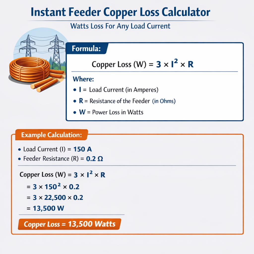
Instant Feeder Copper Loss Calculator (Watts Loss for Any Load Current)
Theory and core formulas for copper feeder watt losses
Power loss in copper feeders is dominated by resistive heating governed by Ohm's law and Joule’s law. The base calculation for instantaneous real power dissipated as heat in a conductor is: P_loss = I2 × R Where:- I is the instantaneous RMS current through the conductor (A)
- R is the electrical resistance of the conductor in ohms (Ω)
- Single-phase two-conductor feeder (supply + return): P_total = 2 × I2 × r × L
- Balanced three-phase (three phase conductors): P_total = 3 × I2 × r × L
- Three-phase four-wire with neutral carrying unbalanced current: P_total = I2 × (sum of resistances of each conductor) (compute per conductor)
Variable definitions, typical values, and temperature corrections
Key variables and typical constants used in feeder copper loss calculations:- ρ20 — Electrical resistivity of pure copper at 20 °C: 1.7241 × 10⁻⁸ Ω·m (typical reference).
- α — Temperature coefficient of copper at 20 °C ≈ 0.0039 /°C.
- r20 — Conductor resistance per unit length at 20 °C (Ω/m) = ρ20 / A, where A is cross-sectional area (m²).
- RT — Resistance at operating conductor temperature T (°C): RT = R20 × [1 + α × (T − 20)].
- I — RMS load current (A).
- L — One-way conductor length (m). For round trip multiply by two where return conductor carries same current.
- k_AC — AC resistance correction factor for skin and proximity effects (dimensionless).
Practical tables: common conductor resistances and loss per unit length
| Conductor Size (mm²) | Approx. Diameter (mm) | R20 (Ω/km) | R20 (Ω/m) | Typical R75 (Ω/km) |
|---|---|---|---|---|
| 1.5 | 1.38 | 12.10 | 0.01210 | 13.92 |
| 2.5 | 1.78 | 7.41 | 0.00741 | 8.52 |
| 4 | 2.26 | 4.61 | 0.00461 | 5.30 |
| 6 | 2.76 | 3.08 | 0.00308 | 3.55 |
| 10 | 3.57 | 1.83 | 0.00183 | 2.11 |
| 16 | 4.51 | 1.15 | 0.00115 | 1.33 |
| 25 | 5.64 | 0.727 | 0.000727 | 0.84 |
| 35 | 6.69 | 0.524 | 0.000524 | 0.607 |
| 50 | 7.98 | 0.387 | 0.000387 | 0.449 |
| 70 | 9.50 | 0.268 | 0.000268 | 0.311 |
| 95 | 11.10 | 0.193 | 0.000193 | 0.224 |
| 120 | 12.40 | 0.153 | 0.000153 | 0.178 |
| 150 | 13.70 | 0.124 | 0.000124 | 0.144 |
| 185 | 15.00 | 0.101 | 0.000101 | 0.118 |
| 240 | 17.00 | 0.078 | 0.000078 | 0.091 |
- R20 values are rounded typical industry figures from copper property tables; units shown.
- R75 is R at 75 °C computed by R75 ≈ R20 × (1 + 0.0039 × 55) ≈ 1.2145 × R20.
- Always verify with cable manufacturer or standard tables for precise design.
| Load Current (A) | Conductor 10 mm², L = 100 m, R20=1.83 Ω/km | Conductor 50 mm², L = 100 m, R20=0.387 Ω/km | Conductor 95 mm², L = 100 m, R20=0.193 Ω/km |
|---|---|---|---|
| 50 | P=50²×(0.00183×100)=50²×0.183=457.5 W | P=50²×(0.000387×100)=50²×0.0387=96.75 W | P=50²×(0.000193×100)=50²×0.0193=48.25 W |
| 100 | 1830 W | 387 W | 193 W |
| 200 | 7320 W | 1548 W | 772 W |
| 400 | 29,280 W | 6,192 W | 3,088 W |
Step-by-step procedure for an instant feeder copper loss calculation
Follow these steps to generate an accurate watt loss estimate quickly:- Identify conductor cross-sectional area (mm²) and one-way length L (m).
- Obtain R20 (Ω/m) for the conductor from manufacturer or standard tables.
- Correct resistance to operating conductor temperature T: RT = R20 × (1 + α × (T − 20)).
- Adjust for AC effects if significant: R_eff = k_AC × RT.
- Compute per conductor resistance for the run: R = R_eff × L.
- Apply P_loss per conductor: P = I2 × R. Multiply by number of carrying conductors to get total copper loss.
- Report loss in watts and optionally convert to kW and percentage of delivered power for efficiency assessment.
AC correction, skin effect and proximity factor
At 50/60 Hz, for typical stranded cables used in building and distribution, DC resistance is a good approximation up to moderate conductor sizes. However, for large circular conductors, busbars, and multi-layer strands, skin and proximity effects increase effective resistance. Guidance:- k_AC ≈ 1.0–1.03 for conductors up to ~70 mm² in typical stranded constructions at 50/60 Hz.
- For conductors > 120 mm² or solid large conductors and busbars, compute k_AC using standards or software; k_AC can reach 1.1–1.3 depending on geometry and frequency.
- Standards such as IEC technical reports and manufacturer data include methodologies to derive AC resistance factors for specific constructions.
Real example 1 — Single-phase feeder, lighting circuit
Problem statement:- Single-phase load: 32 A (RMS) continuous.
- Feeder conductor: 10 mm² copper, one-way length L = 30 m (so round-trip 60 m for supply + return).
- Assume conductor operating temperature 60 °C. Use α = 0.0039 /°C.
- R20 for 10 mm² = 1.83 Ω/km = 0.00183 Ω/m.
- Neglect skin/proximity (k_AC ≈ 1.0).
- Total copper loss ≈ 130 W at 32 A in the 10 mm² feeder (round trip), at 60 °C.
- Per-kilowatt comparison: if load delivers 7.04 kW (32 A × 230 V), copper loss ≈ 130 W represents ≈ 1.85% of delivered power.
- If the return conductor differs in size or shares with other circuits, compute conductor-by-conductor losses.
- For short feeders and moderate currents, heating effect is small; for long runs or higher currents, consider increasing conductor size.
Real example 2 — Balanced three-phase feeder to motor
Problem statement:- Three-phase balanced load: I_phase = 200 A (RMS) per phase (line current).
- Feeder conductors: 95 mm² copper, one-way length L = 75 m.
- Assume conductor temperature 75 °C. Use α = 0.0039 /°C.
- R20 for 95 mm² = 0.193 Ω/km = 0.000193 Ω/m.
- Assume k_AC = 1.05 to account for moderate AC effects on large conductors.
- If the line-to-line voltage is 400 V, total apparent power S ≈ √3 × V_LL × I = 1.732 × 400 × 200 ≈ 138.6 kVA.
- Copper loss as percentage of apparent power ≈ 2.214 kW / 138.6 kW ≈ 1.6% (useful for network efficiency assessment).
- Applying k_AC increased losses; using k_AC = 1.0 yields about 2,108 W showing sensitivity to AC effects.
- Designers often target copper loss percentages depending on feeder criticality; heavy industrial feeders may accept low-percent losses while long distribution feeders may require upsizing.
Advanced considerations for accurate instant calculations
Factors to include for higher-fidelity feeder loss calculations:- Operating temperature profile along the feeder (ambient, grouping, insulation rating).
- Partial load profiles: compute losses as function of I(t) and integrate for energy loss over time: E_loss = ∫ I(t)² × R dt.
- Skin and proximity effects for multi-layer stranded conductors and closely spaced phases (use standard formulas or finite-element tools).
- Neutral conductor carrying unbalanced currents (compute neutral loss separately).
- Reactive currents and harmonic content: harmonics increase RMS current and can increase losses disproportionately. For nonsinusoidal currents compute I_RMS and use I_RMS² in loss formula.
- Temperature coefficient variations for alloys or low-temperature copper variants.
- Annual energy loss (kWh/year) = P_loss (kW) × operating hours per year.
- Monetary cost = Energy loss × energy price (currency/kWh). This is useful when deciding whether to upsize conductors economically.
Example — Annual energy cost comparison (continuation of Example 2)
If the feeder in Example 2 operates 2,500 hours/year and energy cost is $0.12/kWh:- Annual energy loss = 2.214 kW × 2,500 h = 5,535 kWh/year.
- Annual cost = 5,535 kWh × $0.12/kWh = $664.20/year.
Implementation checklist for an instant feeder copper loss calculator tool
Essential inputs:- Conductor cross-section (mm²) or AWG number.
- Conductor length (one-way) in meters.
- R20 or automatic lookup from table.
- Operating conductor temperature (°C).
- Load current (A) — allow time-varying or harmonic spectrum input for advanced calculators.
- System type: single-phase, three-phase balanced, or multi-conductor with neutral.
- k_AC option for AC correction (default 1.0 with guidance).
- Per-conductor resistance at chosen temperature (Ω/m and Ω total).
- Instant copper loss in watts per conductor and total feeder loss.
- kW loss, energy per hour/day/year, and monetary cost over specified period.
- Percentage loss relative to delivered power.
- Suggestions for conductor upsize alternatives with computed loss reductions.
Standards, normative references and authoritative resources
Key standards and references to consult for design and normative methods:- IEC 60287 — Electric cables — Calculation of the current rating (addresses cable heating and loss considerations). See IEC official pages for details: https://www.iec.ch/
- IEEE Std 399 — IEEE Recommended Practice for Industrial and Commercial Power Systems Analysis (system studies and feeder design): https://standards.ieee.org/
- Copper Development Association (CDA) — Material property tables and conductor resistivity: https://www.copper.org/
- NIST reference for material properties and constants: https://www.nist.gov/
- IEC/TR and manufacturer application notes for AC resistance (skin and proximity) and cable grouping correction factors.
- IEC technical publications and application guides for cable derating.
- Manufacturer datasheets for insulated cables (e.g., Prysmian, Nexans, NKT) with precise resistance vs. temperature.
- Textbooks on power system analysis for modeling feeder losses and voltage drop (e.g., IEEE literature and industry handbooks).
SEO and practical deployment tips for an instant feeder loss webpage or calculator
When publishing an instant feeder copper loss calculator online, optimize for discoverability:- Use keywords naturally: "feeder copper loss calculator", "watts loss", "I²R loss", "feeder watt loss per current", "copper feeder loss calculator".
- Provide machine-readable output (JSON) for integration with other tools and quick automation.
- Include sample downloadable CSV tables of conductor resistances and common scenarios.
- Offer "copyable" worked examples (as above) to increase on-page time and authority.
- Reference normative standards with links and versions to boost trust and reduce bounce rate from technical users.
Summary of formulas and quick reference
Core calculation set:Resistance per unit length at 20 °C:
r = ρ20 / A
Resistance at operating temperature T:
RT = R20 × (1 + α × (T − 20))
Total resistance for conductor of length L:
R = r_T × L
Instant copper loss (single conductor):
P = I2 × R
Total feeder copper loss depends on configuration:
Single-phase two-wire: P_total = 2 × I2 × R_one-way
Balanced three-phase: P_total = 3 × I2 × R_phase
Final notes and recommended practice
- Always verify resistances with manufacturer tables; small differences in R cause proportional changes in loss.
- When harmonics are present, compute the true I_RMS and use I_RMS² for loss calculations.
- For lifetime cost decisions, compare capital cost of upsizing conductors versus annual energy and maintenance savings using the examples shown.
- Document assumptions (temperature, k_AC) clearly when reporting calculated losses for design approval.
- IEC 60287 series — Electric cables — Calculation of the current rating. International Electrotechnical Commission. https://www.iec.ch/
- IEEE Standards Association — power systems and feeder design standards. https://standards.ieee.org/
- Copper Development Association — Copper Properties and Resistivity. https://www.copper.org/
- NIST — Reference values for material properties. https://www.nist.gov/
- Manufacturer cable data sheets (e.g., Prysmian Group, Nexans) — consult latest technical catalogs for exact conductor resistance at temperature.