This article explains calculating available fault current at emergency panels including generator contribution and standards
Methods cover utility and generator impedance, step-up transformers, harmonics, protective device coordination considerations and calculations
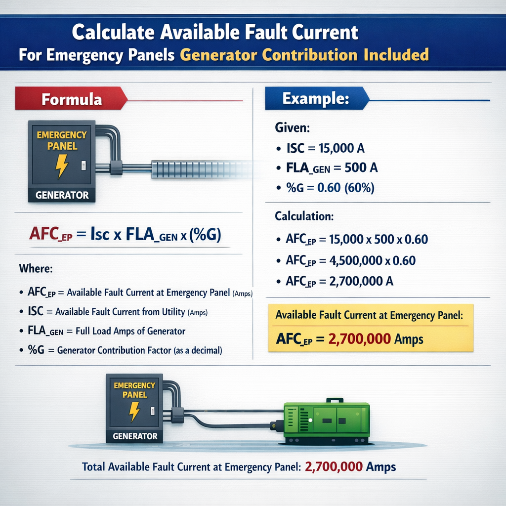
Available 3‑Phase Fault Current at Emergency Panel (Including Generator Contribution)
Overview of available fault current for emergency systems
Available fault current at an emergency panel is the prospective short-circuit current that can flow at the panel terminals during a fault, accounting for contributions from the utility (or upstream grid) and the on-site generator(s). Emergency systems are unique because the generator contribution often persists for several cycles (subtransient, transient, and steady-state periods), and protective device ratings and coordination must reflect the highest initial (subtransient) contribution.
Key theoretical concepts and assumptions
Three-phase vs. unbalanced faults
- Three-phase symmetrical faults are typically used to size interrupting ratings because they produce the highest currents in many configurations.
- Single-line-to-ground and line-to-line faults require sequence-network analysis; generator zero-sequence impedance and neutral grounding determine ground-fault magnitude if the generator is isolated.
Time frames of generator contribution
- Subtransient period (I''): the first few cycles after fault; highest magnitude. Use generator subtransient reactance X"d (percent).
- Transient period (I'): lasts tens to hundreds of cycles; defined by X'd.
- Steady-state (I): long-duration; limited by synchronous reactance Xd or AVR limits.
Thevenin equivalent method and basic formulas
The standard approach is to form Thevenin equivalents for the utility and generator as seen from the fault point, convert per-unit or percent impedances to ohms on a common base, then compute individual current contributions. For three-phase faults, the scalar currents can be added when the sources are in phase (practical approach for magnitude estimation).
Fundamental formulas (use consistent units):
Explanations:
- V_LL — line-to-line nominal voltage at the fault location (volts).
- S_base — apparent power base for the equipment or machine (VA).
- X_percent — reactance expressed as percent on the equipment's own base (%). For generators this is X"d for subtransient current.
- Z_th — Thevenin equivalent impedance (ohms) as seen from the fault point; includes series impedances (transformers, cables, generator internal reactance).
- I_sc — symmetrical short-circuit current (A) for a three-phase fault.
Common formulas in HTML form
Use these when converting % impedances and computing currents:
Where 1.732 is an approximation for sqrt(3). All impedances should be in ohms and powers in VA.
Typical equipment impedance tables
| Generator rating (kVA) | Typical subtransient X"d (%) | Typical transient X'd (%) | Notes |
|---|---|---|---|
| 50 – 250 kVA | 10 – 20 | 20 – 40 | Small prime movers; lower inertia, relatively low X" |
| 300 – 750 kVA | 12 – 18 | 18 – 35 | Typical commercial diesel generators |
| 1000 – 3000 kVA | 15 – 25 | 20 – 40 | Large industrial units; larger X" for higher MVA machines |
| 4000 + kVA | 18 – 30 | 25 – 45 | Very large units; values vary widely with design |
| Transformer type | Typical % impedance (Z%) | Comments |
|---|---|---|
| Padmount, 500 – 1500 kVA | 2.5 – 6.0 | Common distribution transformer impedances |
| Power transformer, 5 – 25 MVA | 7.0 – 15.0 | Higher impedance for larger units |
| Small indoor, 45 – 500 kVA | 2.0 – 5.0 | Low percent impedance increases fault currents downstream |
Step-by-step calculation procedure
- Define the fault location and single-line diagram, including transformers, connections, and switchgear. Identify whether the generator is connected directly or through ATS/transformer.
- Choose a common base: typically the fault bus nominal voltage and a convenient kVA (e.g., generator kVA or transformer kVA). Convert all percent impedances to ohms on that base.
- Compute Thevenin impedance for the utility side as seen at the fault bus (includes utility source and transformer impedance, measured or assumed as available short-circuit MVA or percent Z).
- Compute generator internal impedance (subtransient) referred to the fault bus voltage and base.
- Compute individual fault currents using I = V_LL / (sqrt(3) × Z).
- Sum contributions for symmetrical three-phase; for unbalanced faults perform sequence-network analysis and vector summation as required.
- Compare available fault current to interrupting ratings and let-through energy of protective devices; revise coordination as necessary.
Combining utility and generator contributions
For three-phase symmetric faults, if both utility and generator are connected and the fault occurs at a common bus, the total initial available fault current magnitude is commonly approximated by summing the magnitudes of individual contributions:
I_total ≈ I_utility + I_generator
This approximation is valid when both sources are effectively in phase and when using magnitudes for engineering worst-case selection of interrupting devices. For more accurate results, especially when sources have significant phase shifts (e.g., delta-wye transformer introducing phase shift) or when unbalanced faults are considered, perform full complex impedance/phasor addition or sequence-network analysis.
Example 1 — 480 V emergency panel with behind-the-meter generator
Scenario: Emergency panel fed from utility through a 1000 kVA transformer and backed up by a 625 kVA diesel generator connected directly to 480 V switchgear through an automatic transfer switch. We will calculate three-phase available fault current at the emergency panel bus, including generator subtransient contribution.
Given data
- Panel nominal voltage V_LL = 480 V
- Generator rated prime power P = 500 kW, power factor 0.8 → S_g = 500 / 0.8 = 625 kVA
- Generator subtransient reactance X"d = 15% (typical for this size)
- Utility effective available 3‑phase short-circuit current at the panel (as measured or stated) I_u = 10,000 A
- No significant additional series impedance between generator and panel (generator connected close to bus); transformer on utility side included in I_u
Step A — Generator internal impedance in ohms
Compute generator base impedance Z_base (on generator kVA base):
Z_gen = (X"d / 100) × Z_base = 0.15 × 0.36864 = 0.055296 ohm
Step B — Generator three-phase subtransient current
Step C — Utility contribution
Z_u = V_LL / (sqrt(3) × I_u) = 480 / (1.732 × 10000) = 480 / 17320 = 0.02772 ohm
Step D — Total available fault current (three-phase estimate)
Remarks and checks
- Use the highest initial contribution (generator subtransient) when specifying interrupting ratings and let-through values.
- Breaker interrupting rating at the panel must be ≥ I_total with appropriate safety margin and adhere to NEC/IEEE device rating guidance.
- If transformers, cables or ATS add series impedance between sources and fault point, include those impedances and recompute Thevenin equivalents rather than simply summing magnitudes.
Example 2 — 208Y/120 V emergency distribution with step-up generator and unbalanced fault analysis
Scenario: A hospital emergency distribution bus is 208Y/120 V. The onsite generator is a 1500 kVA diesel unit set at 480 V generator terminals feeding the 208 V bus via a step-down transformer. We calculate three-phase and single-line-to-ground available fault currents at a 208 V emergency panel, including the generator subtransient contribution and transformer impedance. Also show effect of neutral grounding.
Given data
- Panel nominal voltage V_LL = 208 V
- Generator rating S_g = 1500 kVA at 480 V (generator terminal)
- Generator subtransient reactance X"d = 20%
- Step-down transformer: 480 V (delta) to 208Y/120 V, 2000 kVA, Z_tr% = 5.75%, delta-wye (introduces 30° phase shift)
- Utility upstream fault level results in I_u (at 208 V bus) = 6000 A (measured or stipulated)
- Neutral grounding: transformer secondary neutral is solidly grounded (through transformer Y), generator neutral is effectively isolated by delta primary; for ground fault the transformer's grounding dominates.
Approach
We will:
- Refer generator subtransient impedance to the 208 V bus.
- Refer transformer impedance and include its percent Z on the 208 V base.
- Compute I_g as seen at 208 V bus and I_u from the utility. Because delta-wye transformer introduces phase shift, strictly speaking phasor sum is required. For worst-case device selection we can conservatively add magnitudes for three-phase faults. For ground faults use sequence network combining (delta winding blocks zero-sequence).
Step A — Convert generator impedance to 208 base
Generator base is 1500 kVA at 480 V. We need generator impedance referred to the 208 V, 3-phase panel base. Choose S_base_common = 1500000 VA (generator rating) and V_base at panel = 208 V.
Z_base_panel = (V_panel × V_panel) / S_base_common = (208 × 208) / 1500000 = 43264 / 1500000 = 0.028843 ohm
Note: This conversion assumes referring generator impedance from 480 V to 208 V while keeping the same MVA base. A more formal approach is to use per-unit transformation: Z_pu stays same if converting using same S_base; admittance scales with square of voltage ratio. The simplified numeric above gives generator Z in ohms on the 208 V base for current calculation at the panel.
Step B — Transformer impedance referred to secondary
Transformer Z% = 5.75% on 2000 kVA base. Convert to ohms on panel base S_base_common (we use 1500 kVA as common base):
Step C — Equivalent series impedance from generator to panel
If generator is at 480 V and connected through the transformer primary, the generator contribution sees transformer impedance in series (referred to panel). Total generator series impedance Z_g_total ≈ Z_gen_on_panel_base + Z_tr_on_common_base = 0.0057686 + 0.00295 = 0.0087186 ohm
Step D — Generator three-phase short-circuit current at panel
Step E — Utility contribution and total (conservative magnitude summation)
Step F — Single-line-to-ground consideration
- Because the transformer secondary is grounded (Y) and the generator primary is delta, zero-sequence current from the generator is largely blocked by the delta, so generator contribution to ground faults at the 208 V bus may be limited.
- Sequence network analysis: zero-sequence current flows through transformer grounding path and utility contribution primarily determines ground-fault magnitude at the secondary bus when generator is delta-connected.
- Therefore for ground-fault switchgear selection, verify the generator neutral arrangement and compute zero-sequence impedances; do not assume the same magnitude as three-phase result.
Practical implications
- Devices on the 208 V emergency panel must be rated for at least ~20 kA interrupting current, or device selection must account for potential higher currents if generator or utility levels are larger.
- Ground-fault protection curves and neutral grounding resistor sizing require full sequence impedance modeling to estimate actual ground current magnitudes.
Practical guidance and corrections
- If percent impedances are given on differing MVA bases, convert using Z_new = Z_old × (S_new / S_old).
- Always use generator subtransient reactance X" for initial fault current calculations for protective device selection.
- Include step-up or step-down transformer percent impedance; when transformers introduce phase shifts (delta-wye), perform vector (phasor) addition when precision is required.
- For multiple generators paralleling, compute equivalent internal impedance of the paralleling set, or compute individual currents and sum phasorially if phase relationships differ.
Selecting equipment ratings and coordination considerations
Key devices affected by available fault current include circuit breakers, fuses, and bus duct. NEC (NFPA 70) requires equipment to be marked with the maximum available fault current at the time of installation, and that devices have interrupting ratings equal to or exceeding that available current.
- Allow margin for measurement uncertainty and future system changes. Typical practice: select interrupting devices with ratings >= 1.1 to 1.25 × measured/calculated I_total.
- Coordination: high generator contribution increases upstream current; re-evaluate coordination curves because generator contribution can sustain high currents longer than utility peaks, affecting upstream reclosing and downstream device operation.
- Consider current-limiting fuses or breakers lower in the distribution to limit let-through energy for downstream equipment.
Standards, codes, and authoritative references
Recommended normative references for fault current calculations and emergency power systems:
- NFPA 70, National Electrical Code (NEC) — requirements for field marking of available fault current and equipment ratings. https://www.nfpa.org/
- NFPA 110, Standard for Emergency and Standby Power Systems — requirements for emergency power systems and transfer equipment. https://www.nfpa.org/
- IEC 60909, Short-circuit currents in three-phase AC systems — standardized methods for fault calculations (widely used internationally). https://www.iec.ch/
- IEEE Std 141 (The Green Book), Recommended Practice for Electric Power Distribution for Industrial Plants — generator grounding and fault contributions. https://standards.ieee.org/
- IEEE Std C37.010 and related power system fault and relay standards — guidance on generator short-circuit testing and performance. https://standards.ieee.org/
Diagnostic checks and measurement validation
- Obtain measured utility short-circuit levels where possible from the utility: available fault MVA or current at the point of interconnection simplifies computations.
- Verify generator X" values from manufacturer transient reactance data or from factory test reports.
- Perform a secondary injection test or use relay test results to validate calculated values for protection settings; field confirmation is best practice.
- Consider harmonic impedance and non-sinusoidal sources only when inverter-based resources or power electronic limited sources are present; standard synchronous machine calculations assume sinusoidal response.
Common pitfalls and mitigations
- Mixing voltage bases without correct conversion — always perform base transformations when combining percent impedances on different MVA bases.
- For ground faults, neglecting zero-sequence paths such as delta-wye transformer blocking can lead to large errors — perform sequence analysis.
- Assuming generator contribution decays immediately — use subtransient time frame for breaker sizing and consider transient persistence for coordination analysis.
- Ignoring transformer phase shift — delta-wye introduces 30° shift; phasor addition is required for precise summation of contributions.
Summary of actionable steps for engineers
- Map the single-line diagram and list all impedances with their bases.
- Select a consistent base (voltage and MVA) and convert impedances accordingly.
- Use generator subtransient reactance for initial available fault current calculations.
- Include transformer and cable impedances in series when computing source Thevenin impedances.
- Compute individual contributions and combine appropriately; for three-phase faults, add magnitudes conservatively or phasorially if required.
- Specify device interrupting ratings >= calculated available fault current plus margin. Mark available fault current at equipment per NEC.
Additional resources and further reading
- IEC 60909 Short-circuit currents — methodology for different fault types and factors (international standard).
- NFPA 70 (NEC) Article 100 and marking requirements, and NFPA 110 for emergency systems — compliance essentials.
- IEEE C37 series and IEEE 141 — guidance for generator testing and power system analysis.
- Manufacturer generator short-circuit data sheets and transient reactance test reports — essential for accurate modeling.