This technical guide covers AWG bending radius calculation, NEC requirements, installation, safety, and best practices.
Engineers, electricians, and inspectors will find formulas, examples, tables, and regulatory guidance for compliance projects.
Bending Radius Calculator — AWG & Cable OD (NEC-oriented guidance)
Overview of bending radius fundamentals for AWG conductors
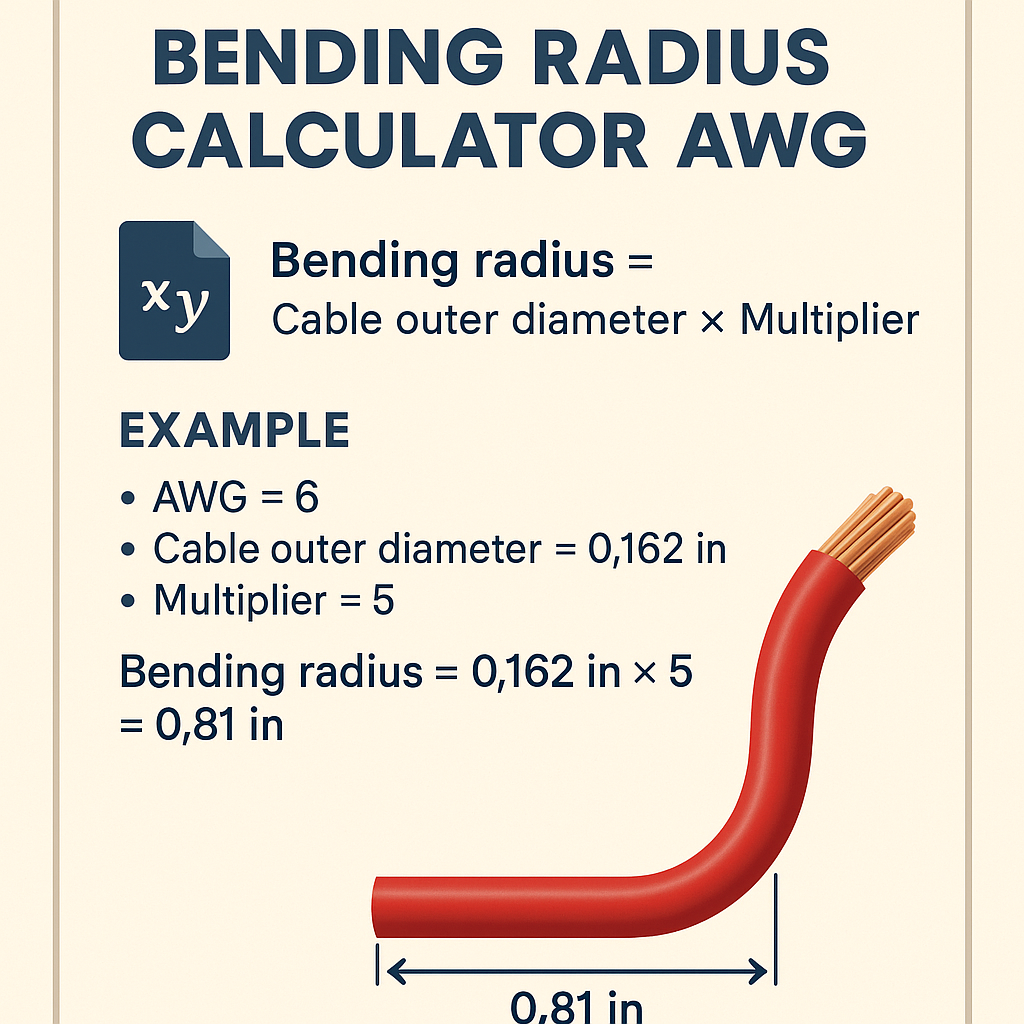
The bending radius is a mechanical limit that prevents conductor damage and preserves electrical performance. For practical design, it is expressed as a multiple of the conductor or cable outer diameter (D).
Why bending radius matters for AWG conductors
- Prevents conductor and insulation cracking, which can cause partial discharge or short circuits.
- Preserves conductor cross-sectional area to avoid increased resistance and heating.
- Ensures safe routing in raceways and equipment per code and manufacturer instructions.
- Reduces risk of mechanical fatigue in flexing applications (e.g., machine cables).
Key formulas and variable definitions
Below are the primary formulas used in bending radius and AWG calculations. All formulas are presented using plain HTML with clear variable explanations and typical values.
AWG conductor diameter (inches):
d_in = 0.005 × 92((36 - AWG)/39)
- d_in: conductor diameter in inches
- AWG: American Wire Gauge number (integer, smaller AWG = larger conductor)
- Typical values: AWG 12 → d_in ≈ 0.0808 in; AWG 10 → d_in ≈ 0.1019 in
AWG conductor diameter (millimetres):
- d_mm: diameter in millimetres
- Typical values: AWG 12 → d_mm ≈ 2.05 mm; AWG 10 → d_mm ≈ 2.59 mm
Copper conductor cross-sectional area (approx):
A_mm2 = π × (d_mm / 2)2
- A_mm2: approximate circular cross-sectional area in square millimetres
- Note: stranded conductors have strand gaps; use equivalent solid conductor area for electrical calculations.
Minimum bending radius (general multiplier rule):
- R_min: minimum bend radius (same units as D)
- k: bending multiplier, dependent on conductor/cable type (see tables below)
- D: outer diameter of insulated conductor or cable assembly (mm or in)
- Typical k values: 3, 4, 6, 8, 12 depending on flexibility and construction
Practical values and AWG tables
Use the following extensive table of common AWG sizes, conductor diameters, approximate cross-sectional areas, and sample outer diameters for typical insulation. These values are for design reference; always confirm with manufacturer data and applicable codes.
| AWG | Conductor Dia (in) | Conductor Dia (mm) | Approx Area (mm²) | Typical Insulated OD (mm) | Typical Insulated OD (in) |
|---|---|---|---|---|---|
| 14 | 0.0641 | 1.63 | 2.08 | 2.8 | 0.110 |
| 12 | 0.0808 | 2.05 | 3.31 | 3.3 | 0.130 |
| 10 | 0.1019 | 2.59 | 5.26 | 3.9 | 0.154 |
| 8 | 0.1285 | 3.26 | 8.37 | 4.7 | 0.185 |
| 6 | 0.1620 | 4.11 | 13.3 | 5.8 | 0.228 |
| 4 | 0.2043 | 5.19 | 21.2 | 7.5 | 0.295 |
| 2 | 0.2576 | 6.54 | 33.6 | 9.5 | 0.374 |
| 1/0 | 0.3249 | 8.25 | 53.5 | 12.0 | 0.472 |
| 2/0 | 0.3648 | 9.27 | 67.4 | 13.5 | 0.531 |
Recommended bending multiplier table by cable type
These recommended multipliers are used widely in industry as conservative guidance. Confirm with product datasheet and local code amendments.
| Cable Type | Typical k (multiplier) | Application Notes |
|---|---|---|
| Single insulated conductor (rigid, fixed) | 3 | Low-voltage branch circuits; avoid sharp corners on termination. |
| Flexible cord (machine cord) | 4 | Dynamic applications; avoid repeated flex beyond rating. |
| Multi-core sheathed power cable | 6–8 | Sheath thickness and conductor fill increase required radius. |
| Armoured cable / metal-sheathed | 10–12 | Stiff construction requires larger radius; use proper bend fittings. |
| Large power cable (EHV, large cross-section) | 8–12 | Follow manufacturer; consider cable reel and installation tooling. |
NEC and international regulatory context
National Electrical Code (NEC) emphasizes installed wiring must not be subject to physical damage and must follow listed/labelled wiring methods and manufacturer instructions. The NEC provides performance and safety requirements; specific bending radius values are often delegated to manufacturer data and recognized standards.
Key normative references and authorities
- NFPA 70, National Electrical Code (NEC) — guidance on wiring methods and installations: https://www.nfpa.org/nec
- Underwriters Laboratories (UL) product listings and installation guidelines: https://www.ul.com
- International Electrotechnical Commission (IEC) standards related to cable construction and testing: https://www.iec.ch
- IEEE standards and technical papers for electrical installation practice: https://www.ieee.org
- Engineering Toolbox reference charts for AWG to diameter conversion: https://www.engineeringtoolbox.com/awg-wire-gauge-d_731.html
Practical compliance approach: follow NEC Articles relevant to the wiring method (e.g., Articles 300–399), use listed cable assemblies, and obey manufacturer-specified minimum bend radii. Document deviations with engineering justification and risk assessment.
Measurement methodology: determine D (outer diameter)
To compute minimum bending radius, measure or obtain the overall insulated outer diameter D. For stranded conductors or multi-core cable, use the cable outer sheath diameter.
How to measure
- Use calipers to measure outside diameter at multiple locations; take the maximum measurement as D.
- For multi-core sheathed cables, measure the sheath outer diameter, not individual conductor diameters.
- If only conductor size is known, estimate D = conductor dia + 2 × insulation thickness. Use manufacturer data for insulation thickness.
- For bundled conductors or jacketed assemblies, use the manufacturer’s overall cable OD.
Best installation and engineering tips
Adopt the following best practices to meet NEC safety intent and maximize cable service life.
- Always check manufacturer data for listed minimum bend radius; where manufacturer guidance exists, it controls over generic rules.
- Use larger bend radius than the minimum when in doubt; increasing R by 25–50% reduces stress significantly.
- Install cable using proper mandrels, bend supports, or factory bend fittings for armoured constructions.
- Avoid bending at fixed angles near terminations; leave service loops where appropriate for maintenance.
- Account for conductor insulation creep or cold flow over time in long-term installations.
- For conduit pulls, calculate conduit fill and friction; tight bends increase pull tension and risk of conductor damage.
- Document bend radii in drawings and installation checklists for quality assurance and inspection.
Worked example 1: AWG 12 single insulated conductor in fixed installation
Problem statement: Determine minimum bend radius for an AWG 12 copper conductor with common PVC insulation in a fixed branch-circuit installation.
Given
- Conductor: AWG 12 copper
- Insulation: typical PVC, assumed insulation thickness = 0.6 mm per side (typical for building wire)
- Use conservative multiplier k = 3 (single insulated conductor, fixed)
Step-by-step calculation
1) Calculate conductor diameter using AWG formula.
d_in = 0.005 × 92((36 - 12)/39)
Compute exponent: (36 - 12)/39 = 24/39 ≈ 0.6154.
920.6154 ≈ 16.16 (approx; use calculator).
d_in ≈ 0.005 × 16.16 = 0.0808 in.
Convert to mm: d_mm = 0.0808 × 25.4 ≈ 2.05 mm.
2) Estimate overall insulated diameter D.
Assume insulation thickness is 0.6 mm per side → added diameter = 2 × 0.6 = 1.2 mm.
D = conductor dia + insulation additions = 2.05 mm + 1.2 mm = 3.25 mm.
3) Apply bending multiplier k = 3.
R_min = k × D = 3 × 3.25 mm = 9.75 mm.
Round to practical value: R_min ≈ 10 mm (≈ 0.394 in).
Result and commentary
The minimum bending radius for AWG 12 with the assumed insulation is approximately 10 mm. Always validate with the cable manufacturer and, for conduit installations, ensure the conduit bend radius meets raceway fill and pulling requirements.
Worked example 2: Multi-core sheathed cable with AWG 4 conductors for a feeder
Problem statement: Calculate minimum bending radius for a 3-conductor sheathed power cable, each conductor AWG 4, used as a fixed feeder. Use conservative k = 8 for multi-core sheathed cables.
Given
- Conductors: AWG 4 copper, typical insulated conductor OD ≈ 7.5 mm overall assembly OD (from table).
- Cable: 3-core with sheath; manufacturer lists overall cable outer diameter D = 18.0 mm (typical large sheathed cable).
- Use k = 8 (multi-core sheathed conservative).
Step-by-step calculation
1) Use manufacturer-specified overall cable diameter D = 18.0 mm directly. This avoids approximations based on individual conductors.
2) Apply bending multiplier:
R_min = k × D = 8 × 18.0 mm = 144.0 mm.
3) Convert to inches if required:
144 mm ≈ 5.67 in.
Result and commentary
Minimum bending radius: 144 mm (5.67 in). For large power cables, this radius ensures no sheath crushing or conductor deformation. During installation, use large-diameter mandrels or factory elbow fittings and confirm that pulling equipment can support the required radius without exceeding permissible pull tensions.
Special considerations: flexible cables, repeated flexing, and environmental effects
Cables that are dynamically flexed (robotics, moving machines) require rated flexible conductors and significantly larger radii than static installations. Fatigue life correlates strongly to bending radius and cycle count.
- Flexible multicore cable: increase R by at least 25% beyond static recommendation; many manufacturers specify R = 7–10 × D for dynamic applications.
- Low temperatures: material stiffening reduces allowable bend; increase R per manufacturer guidance.
- High temperatures: insulation softening may occur; avoid small radii that deform the insulation.
Calculating bend radius in conduit systems and pull planning
When pulling cable through conduit, the internal conduit bend radius and the number of bends strongly influence pull tensions and allowable cable selection. Use recommended conduit bending radii and plan for intermediate pull points where necessary.
Pull tension and friction considerations
- Tight bends increase friction; use lubricant where permitted by the cable listing and NEC allowances.
- Calculate total pulling tension using the capstan equation for multiple bends if needed; consult cable manufacturer for maximum allowable tensile load.
- Use pulley blocks and large-radius sheaves during installation to avoid exceeding the R_min at points of contact.
Inspection, verification, and documentation
Post-installation verification is part of compliance. Inspect bends visually and measure critical locations with a radius gauge or template.
- Record the location and radius of the smallest bends in installation reports.
- Photograph critical terminations showing bending clearance and support hardware.
- Cross-check with manufacturer installation sheets and NEC requirements during inspection.
Risk assessment and engineering deviations
When a design constraint necessitates bends tighter than standard recommendations, perform a documented engineering analysis and obtain approvals from authority having jurisdiction (AHJ). Analysis should include mechanical stress calculations, electrical performance checks, and lifecycle impact assessment.
Mitigation strategies for tight spaces
- Use smaller-gauge or higher-flexibility alternatives if allowed by load calculations.
- Change routing to increase radius or use pre-formed factory bends and fittings.
- Replace sheathed multi-core with individually routed conductors where allowed and practical.
Practical checklists for installers
- Verify AWG size and insulation type before bending.
- Confirm overall cable OD from the manufacturer.
- Calculate R_min = k × D using the manufacturer’s recommended k where provided.
- Use mandrels, bend fixtures, and strain reliefs as required.
- Document and photograph bends and retain installation records for inspection.
References and normative sources
- NFPA 70, National Electrical Code (NEC) — https://www.nfpa.org/nec
- Underwriters Laboratories (UL) — product and installation listings: https://www.ul.com
- IEC standards portal — https://www.iec.ch
- Engineering Toolbox AWG charts and formulas — https://www.engineeringtoolbox.com/awg-wire-gauge-d_731.html
- IEEE Xplore digital library for technical papers on conductor stress and lifecycle: https://ieeexplore.ieee.org
- Manufacturer datasheets and installation guides (example: major cable manufacturers such as Prysmian, Nexans, Belden) — consult product-specific documentation.
Final recommendations and actionable checklist
- Always prioritize manufacturer-specified minimum bend radii; they override generic rules.
- Where manufacturer data does not exist, use conservative multipliers (k) listed in the tables above.
- Measure and use actual cable OD for computations; do not rely only on conductor AWG for multi-core assemblies.
- For dynamic applications and extreme temperatures, consult manufacturer and choose cables rated for flexing and environmental conditions.
- Keep records of calculations, manufacturer instructions, and inspection evidence to demonstrate compliance with NEC and local regulations.
Adopting the engineering practices described here will reduce installation risk, ensure electrical performance, and simplify code compliance reviews. For any ambiguous or critical installations, engage the cable manufacturer and the AHJ early in the design process to confirm acceptable bending, pulling limits, and installation practices.