This document explains transformer kVA sizing to prevent undersizing from demand load calculators with growth.
Engineers require margin calculations, diversity factors, and thermal constraints for reliable infrastructure planning and compliance.
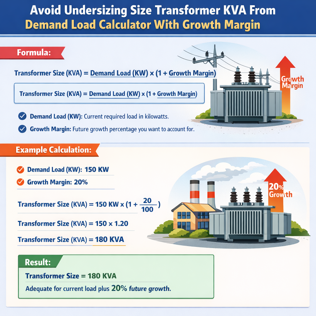
Transformer kVA Sizing from Demand Load with Growth Margin (Avoid Undersizing)
Background and risk of undersizing transformers
Undersizing a transformer relative to the calculated demand load results in excessive voltage drop, thermal overload, reduced equipment life, nuisance protection trips, and potential system instability. Many demand calculators produce a nominal demand figure that excludes realistic growth margins, future loads, or conservative diversity corrections. Designers must therefore translate calculated demands into a conservative, standards-compliant transformer selection that incorporates growth, diversity, starting conditions, and site-specific thermal limits.
Key principles for transformer kVA selection
- Use connected load and demand factors to derive realistic operating load rather than relying solely on nameplate sums.
- Apply power factor corrections when loads are inductive or capacitive; select transformer kVA based on apparent power, not only real power.
- Include a documented growth margin (typically 10–40% depending on project type) to accommodate foreseeable load increases.
- Consider starting currents, inrush, and harmonics—these influence both short-term thermal stresses and long-term temperature rise.
- Match transformer impedance and protection coordination to the upstream and downstream equipment to avoid nuisance tripping and ensure selectivity.
Fundamental formulas and variable explanations
Presenting formulas using plain HTML elements. Each formula is followed by definitions and typical values.
Three-phase apparent power (kVA) from current:
- V_LL = Line-to-line voltage (V). Typical values: 400 V (Europe), 480 V (North America industrial), 11 kV, 33 kV for distribution.
- I = Phase current (A).
- √3 ≈ 1.732 (constant for balanced three-phase systems).
Convert connected real power to apparent power:
- Connected_kW = Sum of connected real powers (kW).
- PF = Power factor (decimal). Typical values: 0.9–0.95 for commercial lighting and loads, 0.8–0.9 for mixed industrial loads, 0.7–0.85 for motor-dominated loads.
Demand-adjusted required kVA with growth margin:
- Demand_factor = Fraction representing usage diversity (typical 0.4–1.0 depending on load type).
- Growth_margin = Anticipated future increase (decimal). Typical values: 0.10 (10%) to 0.40 (40%).
Practical selection rule for standard transformer size:
- Service_margin = Additional margin for safety and longevity (typical 1.05 to 1.25).
- Next_standard_size = Round up to nearest commercially available kVA (see standard sizes table below).
Typical values and demand factors for common load types
Use the following tables to convert connected load into realistic demand estimates. Values reflect common engineering practice; consult local code (NEC, IEC) or utility guidelines for mandatory demand factors.
| Load Type | Connected Load Range (kW) | Typical Demand Factor | Typical Power Factor | Notes |
|---|---|---|---|---|
| Residential general (lighting, receptacles) | 0.5–10 | 0.35–0.70 | 0.95 | Diversity usually high; apply appliance diversity |
| Office buildings (lighting, computers) | 5–1000 | 0.4–0.85 | 0.9–0.95 | Peak daytime loads; consider growth for tenant fit-outs |
| Retail / Shopping malls | 10–5000 | 0.45–0.90 | 0.9–0.95 | HVAC can dominate peak; apply separate HVAC demand factor |
| Industrial (motors, compressors) | 10–20000 | 0.6–1.0 | 0.75–0.90 | Large motors reduce diversity; consider starting currents |
| Data centers | 50–20000 | 0.8–1.0 | 0.95+ | High utilization; distributed redundancy often used |
| Hospital / critical facilities | 20–5000 | 0.7–1.0 | 0.9–0.95 | Essential loads require separate UPS and redundancy |
| Standard Distribution Transformer kVA Sizes (Common) | Typical Use |
|---|---|
| 15 kVA | Small residential service or small commercial tenant |
| 25 kVA | Small shops, small offices |
| 37.5 kVA | Medium residential cluster, small retail |
| 50 kVA | Small commercial, small industrial |
| 75 kVA | Medium commercial, small warehouses |
| 100 kVA | Office buildings, large retail, small manufacturing |
| 150 kVA | Medium industrial, data closet clusters |
| 225 kVA | Large commercial centers |
| 300 kVA | Large industrial feeders |
| 500 kVA | Major plant substations |
| 750 kVA, 1000 kVA, 1500 kVA | Utility distribution and large industrial installations |
Thermal, overload, and inrush considerations
Transformer thermal capacity is defined by its temperature rise characteristics and insulation class. A transformer rated for continuous operation at nameplate kVA should not be operated continuously above that rating without considering reduced life or elevated protection settings.
- Continuous loading: Many transformers are rated for 100% continuous loading at specified ambient conditions (e.g., 40 °C). Consult manufacturer's temperature rise curves.
- Overload capability: Typical dry-type and oil-filled transformers tolerate short-term overloads (e.g., 110–150% for limited duration) but must be evaluated against insulation aging and cooling capability.
- Inrush currents: Energization inrush can be 5–12× rated current for minutes; for large transformers, magnetizing inrush can require motor-starting-style analyses to avoid upstream breaker nuisance trips.
- Harmonic heating: Non-sinusoidal loads (VFDs, UPS) cause additional eddy-current and dielectric losses; apply derating per manufacturer or IEEE 519 guidance.
Growth margin sizing strategy
Applying a growth margin is a deterministic way to avoid undersizing. Consider a structured margin decision protocol:
- Assess expected tenant growth and long-term capacity strategy (years 5–10 outlook).
- Set a nominal growth margin based on building class:
- Residential: 10–15%
- Commercial: 15–25%
- Industrial: 10–40% depending on expansion plans
- Data centers/critical: 15–30% for spare capacity and redundancy strategies
- Combine growth margin with service margin to accommodate uncertainty and manufacturer tolerances.
- Round up to nearest standard transformer size; document rationale in design deliverables.
Formula example for selecting size
Using the earlier formula:
Then apply service margin and select next standard size:
- Service_margin typical: 1.05–1.25 (5–25% additional safety)
- Always document assumed Demand_factor, PF, Growth_margin, and Service_margin
Example case 1: Small commercial building
Scenario: A 4,500 m² small commercial building with shop fit-outs. Connected loads estimated from tenant schedule as follows (rounded):
| Load Item | Connected kW | Recommended Demand Factor | Demanded kW |
|---|---|---|---|
| Lighting | 120 | 0.8 | 96 |
| Receptacles/general | 180 | 0.6 | 108 |
| HVAC (central) | 250 | 0.9 | 225 |
| Elevators | 40 | 0.5 | 20 |
| Small motors/other | 60 | 0.7 | 42 |
| Totals | 650 | 491 |
Assumptions:
- Average power factor PF = 0.92 (commercial loads).
- Growth margin = 20% (tenant fit-out and future expansion).
- Service_margin = 1.10 (10% rounding safety).
Step 1 — Apparent kVA after demand:
Step 2 — Apply growth margin:
Step 3 — Apply service margin and select standard size:
Conclusion: For this building, select a 750 kVA transformer. Document assumptions and verify coordination with utility maximum demand agreements and primary voltage. Consider 2N redundancy if tenants require high availability.
Example case 2: Light industrial plant with multiple motors
Scenario: A manufacturing plant has the following connected loads:
| Equipment | Connected kW | Notes |
|---|---|---|
| Three 75 kW motors (continuous, mainline) | 225 | Motor starting current significant |
| One 150 kW compressor | 150 | Intermittent duty |
| Lighting and receptacles | 60 | Demand factor applicable |
| Process heaters (resistive) | 80 | High PF ~1.0 |
| Miscellaneous | 35 | Controls, small machines |
| Totals | 550 |
Assumptions and considerations:
- Motors: Full load PF ~0.85 for large motors. Locked rotor starting currents about 5–7× rated.
- Demand factor: Due to overlapping operations, assume Demand_factor = 0.95.
- Power factor overall: Use PF = 0.88 (weighted mix).
- Growth margin: 15% for production expansion.
- Service_margin: 1.10 (10% rounding).
Step 1 — Apply demand factor to connected kW:
Step 2 — Convert to kVA using PF:
Step 3 — Include motor starting / inrush study margin:
Large motors may require additional short-term capacity; apply a short-duration inrush allowance. Conservative approach: add an inrush margin of 10% to kVA for coordination.
Step 4 — Apply growth margin:
Step 5 — Service margin and standard size:
Selected_kVA = Next_standard_size(825.11) → 1000 kVA (standard large size) or consider parallel transformers: 500 kVA + 500 kVA (N+1) depending on redundancy preference.
Decision rationale: The single 1000 kVA provides headroom, but for operational continuity and maintenance, consider two 500 kVA transformers in parallel with automatic transfer or load-shedding. Coordinate inrush and fault current contributions with protection engineers.
Transformer impedance and fault current implications
Choosing a larger-than-required transformer changes short-circuit contributions and can affect protective device settings. Transformer per-unit impedance (Z%) determines prospective fault current and voltage regulation.
- Lower kVA with same impedance yields higher short-circuit current; larger kVA with same Z% yields proportionally higher fault current—confirm with manufacturer's Z% table.
- Typical distribution transformer Z% values: 2.5%–6.5% depending on size and design. Low impedance units (<4%) give better voltage regulation but higher fault currents.
- Protection coordination: Verify relay and breaker short-time ratings and selectivity for both increased kVA and potential parallel operation scenarios.
| Typical Transformer Z% vs kVA (illustrative) | 15–50 kVA | 75–150 kVA | 225–500 kVA | 750–1500 kVA |
|---|---|---|---|---|
| Typical Z% | 4.5–6.5 | 4.0–6.0 | 3.0–5.5 | 2.5–4.5 |
| Effect on fault current | Lower fault current | Moderate | Higher | Highest |
| Voltage regulation | Worse | Moderate | Better | Best |
Harmonics, derating, and special load types
Non-linear loads increase losses and heating. Transformers feeding VFDs, rectifiers, UPS systems, and other non-linear equipment require special consideration.
- Consider K-factor or harmonic-rated transformers when total harmonic distortion (THD) exceeds manufacturer thresholds.
- Derate transformer capability per manufacturer guidance (e.g., 10–25% derate for high harmonic content).
- Neutral sizing: harmonic loads (especially triplen harmonics) can overload neutrals; verify neutral ampacity and transformer winding configuration (Δ-Y, Y-Y with or without neutral grounding) to avoid neutral overheating.
Standards and regulatory references
Designers must reference relevant national and international standards for transformer selection, protection, and installation. Key standards and guidance include:
- NEC (NFPA 70) — National Electrical Code, Article 450: Transformers. Official site: https://www.nfpa.org/NEC
- IEC 60076 — Power transformers: design, testing, and rating guidance. IEC standards overview: https://www.iec.ch/standards
- IEEE Std C57 series — Recommended practices and standards for transformers (e.g., C57.12.00). IEEE standards: https://standards.ieee.org
- IEEE 519 — Recommended practice for harmonic control in electrical power systems: https://standards.ieee.org/standard/IEEE_519-2014.html
- NEMA TP 1 and NEMA MG1 — Motor and transformer guidelines: https://www.nema.org
Practical checklist before finalizing transformer selection
- Verify connected loads and demand factors; reconcile with historical utility load records if available.
- Confirm power factor assumptions and consider PF correction equipment if PF < 0.9.
- Decide an explicit growth margin range and document the reasoning tied to expected tenant/production growth.
- Evaluate motor starting requirements and perform short-duration inrush analysis if large motors present.
- Assess harmonic content and specify harmonic-rated equipment or derating where necessary.
- Check transformer impedance and coordination with protection devices; calculate short-circuit current contribution.
- Consider redundancy (parallel transformers or N+1) where reliability dictates.
- Ensure compliance with NEC/IEC/IEEE and local utility requirements; obtain utility approval where applicable.
Documentation and specification requirements
Provide a clear specification section in tender documents covering:
- Rated kVA, primary/secondary voltages, vector group, impedance (%)
- Insulation class, temperature rise, cooling method (ONAN, ONAF, dry-type class), and short-time thermal capability
- Tap changer type and range, including under-load tap changer (OLTC) requirements if voltage regulation is critical
- Sound level criteria for indoor installations
- Harmonic rating or K-factor requirement if applicable
- Protection devices, coordination studies, and test certificates (factory tests per IEC/IEEE)
Summary of best practices (actionable)
- Never select transformer kVA solely on connected load sums—always convert to demanded apparent power and include margins.
- Implement a documented growth margin policy on all projects and apply consistently; justify exceptions head-of-engineering approval.
- Coordinate with protection engineers early to ensure selected transformer impedance and ratings do not introduce coordination problems.
- Use manufacturer data for impedance, temperature rise, and short-time ratings rather than relying on generic tables for final acceptance.
- Consider parallel transformer options for reliability instead of oversized single units where operational continuity is critical.
Further reading and authoritative resources
- NFPA 70, National Electrical Code: Official resources and adoption status — NFPA NEC
- IEC 60076 series on power transformers (purchase and technical summaries) — IEC Standards
- IEEE C57 transformer standards and technical guides — IEEE Standards
- IEEE 519-2014 for harmonics — IEEE 519
- Manufacturer technical application notes (e.g., ABB, Siemens, Schneider Electric) — consult product datasheets for impedance and thermal limits
Final engineer's checklist before procurement
- Confirm Required_kVA calculation with documented demand factors and growth margin.
- Obtain vendor short-circuit impedance and thermal performance data for selected kVA.
- Perform protection coordination and inrush simulations; update breaker/meter settings accordingly.
- Verify primary utility service limitations, maximum available short-circuit, and interconnection rules.
- Document maintenance access, sound, ventilation, and fire separation requirements for installation site.
- Include commissioning test plan: ratio, polarity, winding resistance, impedance, and applied voltage tests as per IEC/IEEE.
Careful application of the formulas and conservative use of growth and service margins ensures transformers are not undersized when derived from demand load calculators. Always combine quantitative calculations with practical engineering judgment and reference to applicable standards to achieve a robust and compliant design.