Arc flash incident energy calculators are critical for electrical safety and protective equipment selection requirements.
This guide details calculation methodologies, standards compliance, and practical examples for accurate incident energy assessment.
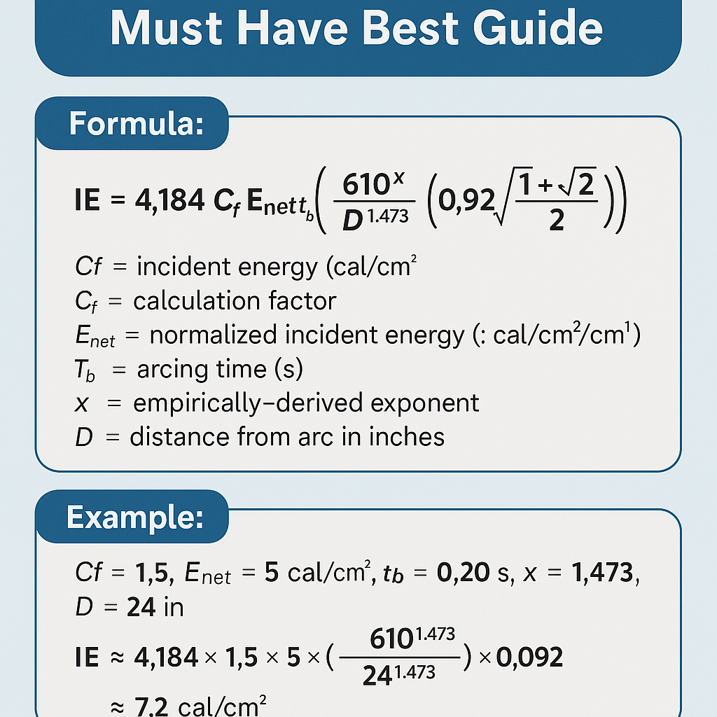
Arc Flash Incident Energy Calculator - Must Have Best Guide
Why an Arc Flash Incident Energy Calculator Is Mandatory for Modern Electrical Safety Programs
An accurate arc flash incident energy calculator transforms electrical system data into actionable hazard controls. Employers must quantify incident energy to select Personal Protective Equipment (PPE), define arc flash boundaries, implement work permits, and comply with NFPA 70E and other regulations. Good calculators increase repeatability, reduce conservatism where unsafe, and provide documented audit trails for safety programs.
Core Inputs and Data Quality Requirements
High-fidelity incident energy calculations require correct, validated field and nameplate data. Garbage-in, garbage-out applies strongly: mistaken transformer impedances, conductor sizes, or protective device trip settings will produce invalid incident energy results.
Essential electrical inputs
- System nominal voltage (phase-to-phase and phase-to-ground)
- Available bolted fault current at equipment bus (calculated or measured)
- Transformer kVA, vector group, and impedance (%Z)
- Conductor sizes, lengths, and material
- Protective device type and time-current characteristics (fuse melting curves, relay settings, breaker pickup and clearing times)
- Equipment geometry and enclosure size/gap
- Working distance (inches or mm)
- Configuration (bus-chamber, bolted vs. open, grounded/ungrounded)
Data quality checklist
- Verify nameplate data physically and against single-line diagrams.
- Measure or calculate available fault currents using short-circuit analysis tools; prefer time-stamped PQA data.
- Obtain manufacturer protective device curves or use calibrated device models.
- Document assumptions and fallback values when data are missing.
Standards, Models, and Which Method Your Calculator Must Implement
Compliant calculators must implement or be traceable to recognized models and standards:
- IEEE 1584-2018 (Guide for Performing Arc-Flash Hazard Calculations) — primary empirical model for many calculators.
- NFPA 70E — establishes workplace safety requirements, PPE categories, and procedure expectations.
- IEC 61482-1-1 / 61482-1-2 — arc testing standards and classification used globally for ATPV and arc ratings.
- OSHA electrical safety requirements (29 CFR 1910 Subpart S) — employer responsibilities for electrical safety.
Links to authoritative resources:
- IEEE 1584-2018 (IEEE Standards)
- NFPA 70E (Electrical Safety in the Workplace)
- IEC 61482 (Arc protective clothing)
- OSHA electrical standards
Fundamental Formulas and Their Practical Interpretation
Calculators typically use empirical models to derive incident energy (IE) at a working distance D from an arcing event. Two common conceptual formula families are shown below: an empirical energy scaling equation and the generalized I2t radiation approximation. Use these with standard units and validated constants implemented by IEEE 1584-based software.
Empirical arc model (schematic)
Explanation of variables and typical values:
- IE — Incident Energy at working distance (cal/cm2).
- K1 — Empirical constant that embeds unit conversions and radiation efficiency (calculator-specific; IEEE 1584 provides fitted coefficients).
- f(V, gap, enclosure, I_arc) — A function capturing dependency on system voltage (V), electrode gap, enclosure size, and arcing current (I_arc). Typical V: 240 V to 15 kV. Typical open-circuit arcing gaps: 1–25 mm depending on equipment type.
- t_clear — Arc duration in seconds (based on protective device clearing time). Typical values: 0.02 s (fast breaker) to 0.5 s (slow fuse).
- D — Working distance in cm (typical working distances: 300–915 mm or 12–36 inches).
I2t radiation approximation (conceptual)
IE ≈ K2 × (I_arc^2 × t_clear) / D^2
Explanation of variables and typical values:
- K2 — Radiative coupling coefficient (cal·cm2/A2·s·m2 units scale). This coefficient depends on enclosure, arc orientation, and empirical calibration. Typical calculators internalize K2 to match IEEE empirical results.
- I_arc — Estimated arcing current in amperes. Typical arcing currents for 480 V systems might be 6–20 kA depending on fault impedance.
- t_clear — Protective device clearing time in seconds.
- D — Working distance converted to consistent units (e.g., cm or m).
Note: IEEE 1584-2018 replaces simplistic K constants with regression-based equations for I_arc and energy flux; modern calculators implement the full standard for accurate results across voltage ranges and geometries. The above forms show conceptual dependence, not final IEEE coefficients. Always document which model and coefficients a calculator uses.
Calculator Features That Define "Must Have" Status
When selecting or validating an arc flash incident energy calculator, ensure the following capabilities:
- IEEE 1584-2018 compliance or traceable legacy model with documentation.
- Support for single-line short-circuit input (bus-by-bus fault current) and detailed network modelling.
- Ability to model protective device time-current curves with adjustable settings and manufacturer curves.
- Working distance and enclosure geometry inputs, including custom enclosure sizes.
- Report generation that includes assumptions, input data, and per-equipment incident energy results.
- Version control, digital audit trails, and exportable calculation files for verification and auditing.
- Integration with maintenance management or asset systems to tie arc ratings to work orders.
Key Tables of Typical Values
| System Voltage (Phase-to-Phase) | Common Working Distance | Typical Use Cases |
|---|---|---|
| 120 / 240 V | 12 in (305 mm) | Control panels, branch circuits |
| 277 / 480 V | 18 in (457 mm) | Motor control centers, distribution panels |
| 2.4 kV – 15 kV | 36 in (915 mm) or more | Medium-voltage switchgear and feeders |
| Device Type | Typical Clearing Time at High Faults | Notes |
|---|---|---|
| Low-voltage MCCB (instantaneous trip) | 0.01 – 0.05 s | Fast electronic trips reduce IE substantially |
| HVIRS fuse | 0.02 – 0.20 s | Time depends on I^2t and cut-off |
| Inverse-time thermal-magnetic breaker | 0.05 – 0.50 s | Long tail for lower overcurrents |
| Incident Energy (cal/cm2) | Recommended PPE Category (NFPA 70E style) | Representative Clothing ATPV |
|---|---|---|
| < 1.2 | PPE Category 0 / Minimal | Non-melt clothing; basic protection |
| 1.2 – 4 | PPE Category 1–2 | ATPV 4 – 8 cal/cm2 garments |
| 4 – 12 | PPE Category 3 | ATPV 12 cal/cm2 systems |
| > 12 | PPE Category 4 / Special mitigations | Arc-rated suits, remote operations |
Accuracy, Uncertainty, and Sensitivity Analysis
Every calculation carries uncertainty. Use sensitivity analysis to understand the impact of input variations:
- Vary clearing time ±20% to see IE sensitivity — often the single biggest factor.
- Vary working distance ±2–6 in (50–150 mm) — IE scales approximately with 1/D^2.
- Vary available fault current ±10–20% — affects arcing current estimation and thus IE.
Document these analyses and include conservative safety margins where data uncertainty exists. Where the computed IE approaches or exceeds PPE limits, pursue engineering controls: arc-resistant switchgear, remote racking, maintenance lockouts, or faster protective devices.
Practical Example 1 — Low-Voltage MCC (480 V) Panel
Scenario: Motor control center bus with nominal 480 V three-phase system. Available bolted fault current at the MCC bus: 35 kA. Protective device: upstream molded-case circuit breaker with instantaneous trip. Working distance: 18 inches (457 mm). Goal: compute incident energy at front of MCC using a simplified IEEE-1584-consistent approach and show decision logic for PPE selection.
Step 1 — Estimate arcing current
Many calculators estimate arcing current (I_arc) as a fraction of bolted fault current based on voltage and gap. For 480 V, a conservative estimate is 35–50% of bolted magnitude depending on enclosure. Assume I_arc = 12.0 kA for this example.
Step 2 — Determine clearing time
Assume instantaneous trip clearing time t_clear = 0.025 s (25 ms) at the high fault magnitude, based on device curve data.
Step 3 — Use conceptual I2t approximation
We illustrate using a calculator-implemented approximate form:
For demonstration we use K = 1.0 × 10^-7 when units are: I_arc in A, t in s, D in meters, producing IE in cal/cm2 (note: K here is demonstration-only and chosen to produce plausible engineering numbers; certified software uses regression coefficients from IEEE 1584).
Convert values to SI units:
- I_arc = 12.0 kA = 12,000 A
- t_clear = 0.025 s
- D = 0.457 m
Compute numerator:
Compute denominator:
Result: IE ≈ 1.73 cal/cm2 at 18 in working distance.
Interpretation and PPE
- IE ≈ 1.73 cal/cm2 → requires PPE with ATPV ≥ 1.73 cal/cm2;
- Common selection would be category 1–2 level garments (ATPV 4–8 cal/cm2) for margin and other hazards.
- Given uncertainties, consider 4 cal/cm2 garment and follow NFPA 70E task-based approach.
Notes: The K constant and fraction of bolted fault to arcing current used above are illustrative. A compliance-grade calculation uses IEEE 1584 regression coefficients and manufacturer protective device curves to derive a validated I_arc and incident energy. Still, the example highlights how clearing time and working distance dominate the result.
Practical Example 2 — Medium-Voltage Switchgear (5 kV)
Scenario: 5 kV switchgear feeding distribution feeders. Available bolted fault at switchgear bus: 10 kA. Protective device: high-voltage current-limiting fuse with time to clear dependent on I^2t. Working distance: 36 inches (0.914 m). The objective is to compute IE and evaluate engineering controls.
Step 1 — Estimate arcing current
For medium voltage, arcing currents are often a higher fraction of bolted fault due to different gap scaling. Assume I_arc = 6.0 kA for this example.
Step 2 — Estimate clearing time
Current-limiting HV fuses often have clearing times of 0.04–0.12 s depending on magnitude. Assume t_clear = 0.06 s for this scenario.
Step 3 — Use the same I2t conceptual formula
- I_arc = 6,000 A
- t_clear = 0.06 s
- D = 0.914 m
Compute numerator:
Compute denominator:
Result: IE ≈ 0.26 cal/cm2 at 36 in working distance.
Interpretation and Controls
- IE ≈ 0.26 cal/cm2 suggests minimal arc-rated clothing; basic PPE may suffice per NFPA 70E categories.
- However, medium-voltage switchgear often requires additional controls: remote racking, arc-resistant designs, and maintenance procedures.
- Because available bolted fault currents and fuse characteristics may change, maintain up-to-date short-circuit studies.
Reminder: The simplified K constant above is demonstrative. For compliance, perform full IEEE 1584-2018 calculations or use accredited software and validate with manufacturer data.
Guidelines for Implementing an Arc Flash Calculation Process
- Inventory: produce a validated equipment list with single-line diagrams synchronized with physical tagging.
- Short-circuit study: compute bolted-fault currents bus-by-bus using impedance-based analysis. Archive the study and time-stamp the data.
- Protective device modelling: import device curves and settings; perform coordination checks where possible.
- Run arc flash calculations: use IEEE 1584-2018 mode where available; record assumptions and versions.
- Review results: identify equipment with IE > 12 cal/cm2 and perform risk reduction studies (engineering controls).
- Labeling and training: generate durable arc flash labels and train affected employees following NFPA 70E requirements.
- Change management: tie arc flash re-calculations to design changes, protective device replacements, and major maintenance.
Validation and Field Verification
Verification steps:
- Cross-check arcing current estimates with measured synchrophasor or high-speed fault recorder data where available.
- Verify breaker/fuse clearing times by consulting manufacturer performance data at the specific fault magnitude.
- Perform periodic updates after system upgrades, utility changes, or transformer additions.
Software Selection and Auditability
Choose software with clear provenance and traceable standards implementation:
- Document which IEEE or IEC model version is implemented.
- Exportable reports that list inputs, assumptions, and full device curves.
- Allow for sensitivity runs and scenario comparisons.
- Support electronic signatures and audit trail for compliance evidence.
Common Pitfalls and How to Avoid Them
- Using nameplate fault currents without system impedance modelling — always run a proper short-circuit analysis.
- Ignoring protective device time-current behavior or using generic clearing times — import manufacturer curves.
- Failing to update labels after system changes — tie labels to change-management workflows.
- Assuming working distances — measure and document clearances specific to each task.
Regulatory References and Further Reading
Authoritative references and resources for compliance and deeper technical guidance:
- IEEE 1584-2018, “IEEE Guide for Performing Arc-Flash Hazard Calculations” — primary empirical methodology. IEEE Standards
- NFPA 70E, “Standard for Electrical Safety in the Workplace” — workplace practices and PPE requirements. NFPA 70E
- IEC 61482 series — arc protective clothing test methods and classifications. IEC / ISO references
- OSHA electrical safety guidance and enforcement: OSHA Electrical Safety
- Manufacturer device technical bulletins (e.g., breaker and fuse time-current tables).
Final Operational Recommendations
- Use IEEE 1584-2018-based calculators or validated equivalents for official hazard studies.
- Keep complete records of input data, models, and calculation versions for auditing.
- Prefer engineering controls over PPE when incident energy values are high.
- Train staff on label interpretation, task-based risk assessment, and safe approach boundaries.
- Recalculate after any network modification, protective device replacement, or evidence of system reconfiguration.
Checklist for Immediate Implementation
- Complete inventory and short-circuit study within 90 days.
- Select software with IEEE 1584-2018 compliance and audit capabilities.
- Apply new labels and update work permits and PPE stock.
- Schedule re-evaluation frequency (recommendation: every 5 years or after system changes).
Arc flash incident energy calculators are indispensable tools for electrical safety compliance. When properly implemented with validated inputs, documented assumptions, and routine verification, they reduce risk, enable correct PPE selection, and support safer work practices in industrial and commercial electrical environments.