This technical guide explains accurate methods for sizing kVAR capacitor banks for fixed or stepped.
Includes formulas, tables, practical examples, normative references, and calculator logic for engineers design commissioning verification.
Capacitor Bank kVAr Sizing Calculator to Achieve Target Power Factor (Fixed or Stepped)
Overview of kVAR Capacitor Bank Sizing and Objectives
Power factor correction aims to minimize reactive power drawn from the utility, reduce losses, and avoid penalties. Correct sizing ensures the plant reaches a target power factor (PF) reliably without overcompensation, resonance or nuisance switching.
Key Inputs and Definitions for a Sizing Calculator
- Active power (P) in kW or MW — measured average or peak depending on correction strategy.
- Initial power factor (PF1, lagging) — measured at the point of common coupling (PCC).
- Target power factor (PF2, usually near unity, e.g., 0.95, 0.98) — utility or design requirement.
- Voltage level (V) — nominal line-to-line or phase voltage affects capacitor bank ratings.
- System frequency (f, typically 50 Hz or 60 Hz) — influences reactance and resonance calculations.
- Harmonic environment and impedance — for detuned designs and harmonic compliance (IEEE 519).
- Choice: Fixed bank or stepped (switched) bank — determines control logic and step sizing.
Fundamental Formulas and Derivations
The basic reactive power required to change power factor from PF1 to PF2 is obtained from real power and tangent of phase angles.
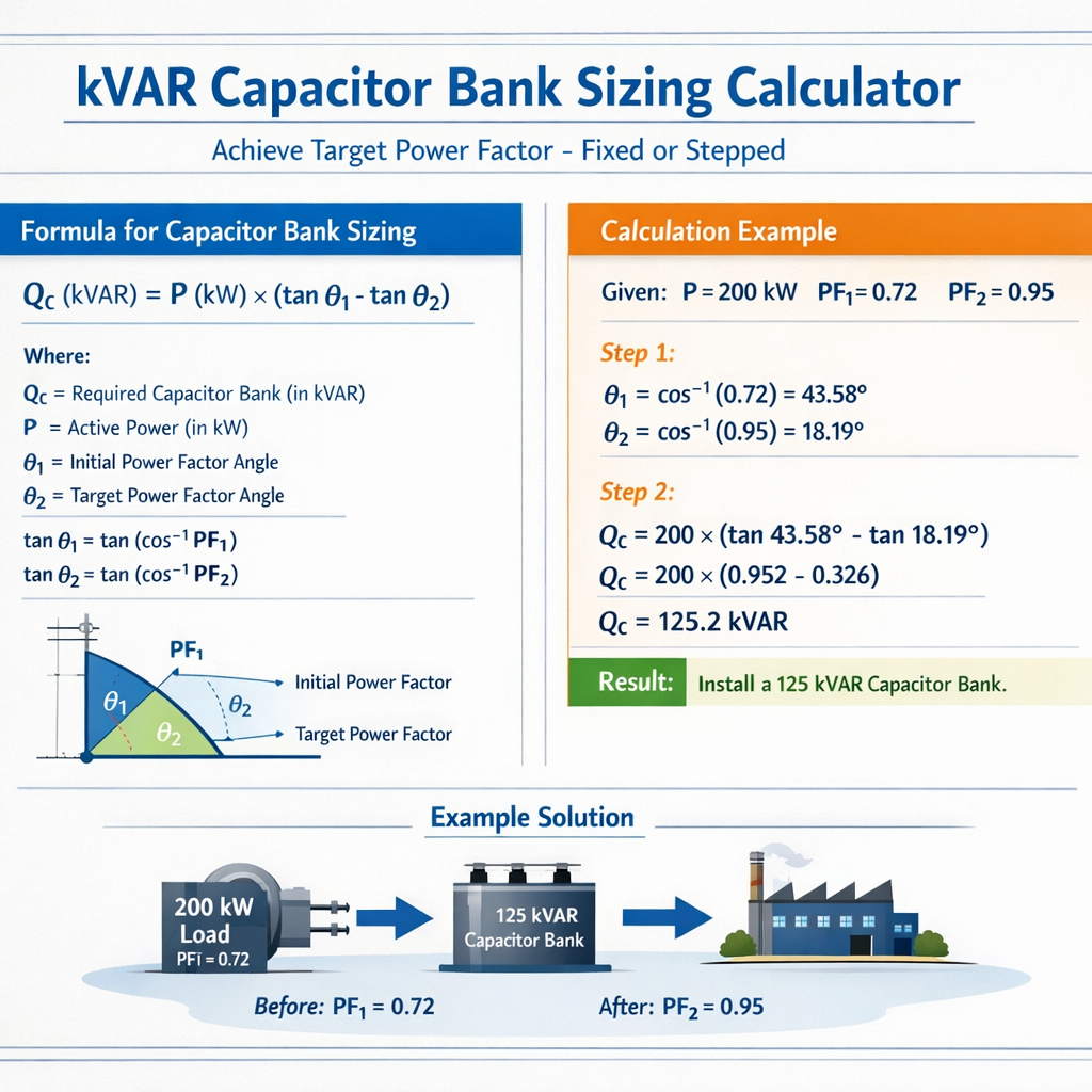
Active formula:
Alternatively, express using apparent powers:
Explanation of Variables and Typical Values
- P (kW): real power; typical industrial values range from tens of kW to several MW.
- PF1: initial power factor (lagging), e.g., 0.70–0.95 depending on load mix.
- PF2: target power factor, often 0.90–0.99; utilities commonly require ≥0.95.
- φ1, φ2: load power factor phase angles in radians or degrees; φ = arccos(PF).
- Qc (kVAR): reactive power compensation required in kilovolt-amperes reactive.
- Voltage (V): e.g., 400 V, 480 V, 11 kV; used to select capacitor units and fuse ratings.
- f: 50 or 60 Hz; affects capacitor reactance XLc = 1 / (2π f C) and detuning reactor values.
Practical Calculator Algorithm and Rounding Rules
- Input P (kW), PF1, PF2, V, f, harmonic levels and system short-circuit MVA (optional).
- Compute φ1 = arccos(PF1) and φ2 = arccos(PF2).
- Compute tan φ1 and tan φ2.
- Compute Qc = P × (tan φ1 − tan φ2).
- Apply safety margin (typically 5–10%) to account for measurement uncertainty and future load growth.
- Select discrete capacitor steps: round to available commercial kvar sizes and plan step switching sequence.
- If harmonics present, compute detuning and select tuned frequency; choose reactor K-factor and filter design accordingly.
- Output: bank kvar sizes, number of steps, recommended fuse/ACB ratings, switching controls and protections.
Rounding and Step Sizing Best Practices
- Prefer smaller step sizes to avoid repeated switching and motor power oscillations; minimum step commonly 5–10% of total bank.
- For stepped banks, choose steps such that no single step overshoots compensation at minimum loading conditions.
- Include an automatic circulating controller with deadband to minimize wear (hysteresis typically 1–3% PF).
- When in doubt, undercompensate slightly or use a fixed bank with tuned reactor if harmonics are high.
Tables of Common Values and Standard Capacitor Sizes
| Nominal Voltage | Typical Single Unit kVAR | Typical kVAR per Phase (Three-phase) | Common Fuse Rating (A) | Typical Dimensions (mm) |
|---|---|---|---|---|
| 400 V | 10, 25, 50, 100 kVAR | 3.3, 8.3, 16.7, 33.3 kVAR/phase | 25–250 A | 200×300×350 |
| 480 V | 6.7, 20, 33, 75, 150 kVAR | 2.2, 6.7, 11, 25, 50 kVAR/phase | 20–200 A | 220×350×400 |
| 11 kV | 100, 200, 400, 800 kVAR | — (typically banked) | — (HV switchgear rated) | Custom outdoor tanks |
| MV (6.6–13.8 kV) | 250–2000 kVAR | — | HV circuit breaker | Pad-mounted or indoor MV cells |
| P (kW) | PF1 (initial) | PF2 (target) | Qc required (kVAR) |
|---|---|---|---|
| 100 | 0.80 | 0.95 | 100 × (tan arccos 0.80 − tan arccos 0.95) ≈ 100 × (0.75 − 0.329) ≈ 42.1 |
| 500 | 0.85 | 0.98 | 500 × (0.728 − 0.203) ≈ 262.5 |
| 1200 | 0.78 | 0.95 | 1200 × (0.799 − 0.329) ≈ 564 |
| 2500 | 0.88 | 0.98 | 2500 × (0.487 − 0.203) ≈ 720 |
Harmonic Considerations, Detuning, and Resonance
Capacitor banks interact with system inductance producing resonant frequencies. When harmonic currents are present, detuned capacitor banks with series reactors (e.g., 7% or 5% reactor) are used to shift the resonant frequency below significant harmonic orders.
Detuned Reactor Design Rule-of-Thumb
Detuned reactors are specified as a percent of capacitor reactance at system frequency, commonly 7% (for 11th harmonic detuning) or 13% (for stronger detuning). Choose detuning to ensure the resonant frequency falls lower than the predominant harmonic frequency.
Where L is reactor inductance and C is capacitance. Use the network short-circuit MVA at PCC to compute system inductance:
X_L (%) = 100 × (X / Z_base) ; or compute L from X = 2π f L.
Harmonic Compliance
- Assess harmonic current spectrum (Ih) and harmonic distortion (THDi).
- Compare expected harmonic current into capacitor with capacitor permissible harmonic current (manufacturer datasheets and IEEE 18 limits).
- Design detuned filters or tuned filters where necessary — tuned filters address specific harmonic orders but add complexity.
- Follow IEEE 519 for allowable harmonic limits and IEC/EN standards for capacitor endurance under harmonic stress.
Protection, Switching Devices and Control Logic
- Switchgear: contactors, vacuum contactors, or vacuum switches for medium voltage banks.
- Fusing: per-phase fuses for low voltage banks (current-rated), consider rejection fuses for fault isolation.
- Protection relays: overcurrent, overvoltage, unbalanced voltage, and residual overcurrent for capacitor faults.
- Controller features: PF setpoint, hysteresis, monitor kW, load blocking (prohibit switching during motor starts), dynamic re-enable delays.
- Safety: include discharge resistors across capacitor elements to safely ground unused units after switching.
Control Algorithm: Fixed vs Stepped
Fixed bank: permanently connected capacitor bank sized to supply a fixed portion of reactive demand. Good for steady loads or when minimizing switching operations.
Stepped (switched) bank: one or more capacitor steps switched in/out to follow load variations. Requires controller to determine step sequence based on PF or reactive power measurement.
Example 1 — Simple Fixed Correction Sizing (Detailed)
Problem statement: An industrial plant operates at P = 1200 kW with measured PF1 = 0.78 (lagging). The utility requires PF2 = 0.95. The supply is 480 V, 60 Hz. Design a fixed capacitor bank size, include margin and select commercial sizes.
Step 1: Compute φ1 and φ2.
Step 2: Compute required Qc.
Qc = P × (tan φ1 − tan φ2) = 1200 × (0.799 − 0.329) = 1200 × 0.470 = 564 kVAR
Step 3: Apply margin for uncertainty and future load growth. Use 7% margin.
Step 4: Select commercial sizes and arrangement. At 480 V, common unit sizes: 33 kVAR, 50 kVAR, 75 kVAR.
Choose combination approximating 600 kVAR: 8 × 75 kVAR = 600 kVAR (three-phase bank).
Step 5: Verify not to overcompensate at minimum loading (if available). If minimum load is 400 kW and PF1 remains similar, Qc_min = 400 × 0.470 = 188 kVAR; 600 kvar would overcompensate potentially causing leading PF at light loading. If minimum load is unknown, use stepped design or reduce fixed bank size.
Step 6: Protection and selection notes:
- Use vacuum contactors rated for inrush and switching operations.
- Install per-phase fuses sized to the capacitor current: I_cap = Qc_phase / (√3 × V). For 600 kVAR at 480 V: I_total = 600 / (√3 × 0.48) ≈ 722 A; per-phase currents and fuse sizing accordingly.
- Consider detuned reactors if harmonics exceed negligible levels; perform harmonic scan.
Example 2 — Stepped Bank Design with Multiple Operating Points
Problem statement: A commercial facility has variable loading between 150 kW and 900 kW. Measured PF1 at 900 kW = 0.82 lagging. Desired target PF2 = 0.98. Design a stepped capacitor bank with minimal switching and no leading PF at minimum load. Use step sizes from available commercial modules: 25, 50, 100 kVAR.
Step 1: Compute Qc for full load (900 kW).
Step 2: Compute Qc for minimum load (150 kW).
Assume PF1 at low load remains 0.90 (often PF improves at light load). Use PF1_low = 0.90 => φ_low = arccos(0.90) ≈ 25.84° ; tan φ_low ≈ 0.484
Step 3: Choose step strategy to avoid leading PF at 150 kW:
- Total needed at full load ≈ 445 kVAR. Round to available combination: 450 kVAR.
- Select steps: 50 + 100 + 100 + 200? Practical distribution: 4 steps = 50, 100, 100, 200 totals 450.
- At minimum load, controller should only connect smallest step(s) to maintain lagging or near-unity PF: 50 kVAR yields Qc_min ≈ 50 kVAR > 42.2 kVAR; check leading risk: if PF1_low is actually 0.95, Qc_min may overcompensate. Design controller with load-blocking and PF feedback to prevent leading operation.
Step 4: Controller logic recommendations:
- Use PF sensor and time-delay logic (inhibit switching during starts or for 30 s after changes).
- Implement minimum time between operations (e.g., 2–3 minutes) and step locking to prevent chattering.
- Load blocking: if real power < 200 kW, limit total connected steps to 50 kVAR to avoid leading PF.
Step 5: Validate via simulated load profiles and adjust step sizes/sequence accordingly. Consider more, smaller steps (e.g., ten × 50 kVAR) if switching frequency is acceptable.
Verification, Commissioning and Measurement Procedures
- Measure baseline PF, kW and kVAR at PCC using calibrated power analyzer over representative intervals (e.g., 1 minute, 15 minutes).
- Install bank and configure controller with conservative initial setpoints and hysteresis.
- Observe switching behaviour for several days across peak and low loads; log PF and kVAR over 24–72 hours.
- Adjust step sizes, blocking thresholds, time delays, and apply additional margin if necessary.
- Perform harmonic analysis and ensure compliance with IEEE 519 limits after bank commissioning.
Detailed Protective Settings and Sizing Formulas for Switching Components
For three-phase bank: I_total ≈ Qc_total × 1000 / (√3 × V_LL)
Fuse selection rule-of-thumb: choose fuse with ampere rating ≥ 1.35 × I_running and suitable breaking capacity. Consult manufacturer tables for inrush and harmonics.
Switchgear dynamic stress: contactors must withstand switching currents including inrush and discharge currents; vacuum switching preferred above certain ratings for longevity.
Common Pitfalls and Mitigation Strategies
- Overcompensation at low loads — mitigate with stepped design, load blocking, or continuous monitoring.
- Resonance with harmonic sources — perform harmonic analysis and detune or install filters.
- Frequent switching causing contactor wear — increase step granularity, implement deadband and minimum on-times.
- Incorrect measurement point — always measure at PCC to capture system effects and utility interactions.
- Ignoring temperature and ambient conditions — choose capacitors with appropriate temperature class and enclosures.
Additional Calculation Examples and Short-Cut Tables
| P (kW) | PF1 | PF2 | Qc (kVAR) = P × (tan φ1 − tan φ2) |
|---|---|---|---|
| 50 | 0.75 | 0.95 | 50 × (1.333 − 0.329) ≈ 50×1.004 ≈ 50.2 |
| 200 | 0.80 | 0.98 | 200 × (0.75 − 0.203) ≈ 109.4 |
| 750 | 0.85 | 0.95 | 750 × (0.728 − 0.329) ≈ 298.5 |
| 1500 | 0.90 | 0.98 | 1500 × (0.484 − 0.203) ≈ 421.5 |
Standards, Guidelines and Authoritative References
Design and commissioning should follow recognized standards and manufacturer guidance. Key references:
- IEEE Std 18 — "IEEE Standard for Shunt Power Capacitors" (specifications for capacitors and mounting). See: https://standards.ieee.org/standard/18-2015.html
- IEEE Std 519 — "IEEE Recommended Practice and Requirements for Harmonic Control in Electrical Power Systems" (harmonics limits). See: https://standards.ieee.org/standard/519-2014.html
- IEC 60831 — "Shunt power capacitors of rated voltages up to and including 1000 V" (capacitance standards). See: https://www.iec.ch/
- IEC 60076 — "Power transformers" (for MV capacitor banks and interactions with transformers). See: https://www.iec.ch/
- Manufacturer technical datasheets: consult capacitor vendors for permissible harmonic currents, temperature classes, and fuse recommendations (e.g., EPCOS/TDK, ABB, Schneider Electric).
- Local utility power factor and billing rules — consult utility tariffs and connection agreements for target PF and penalty thresholds.
Checklist for Implementing a kVAR Sizing Calculator
- Collect accurate P, PF, voltage, and harmonic data at the PCC across representative intervals.
- Decide target PF based on utility and design objectives.
- Choose fixed or stepped topology considering load variability and switching limitations.
- Calculate required Qc using provided formulas and apply margin for growth.
- Assess harmonics and design detuned reactors or filters if necessary.
- Select commercial capacitor sizes, switching gear, fuses, and protective relays.
- Implement control logic: PF setpoint, hysteresis, load-blocking and minimum on-times.
- Commission with logged measurements and adjust configuration based on actual performance.
Final Technical Notes and Advanced Considerations
- Distributed vs centralised capacitors: distributing compensation close to loads reduces feeder currents and losses, but increases switching complexity.
- Reactive power from renewable power electronics: PV inverters and variable frequency drives (VFDs) can supply or absorb vars; coordinate control to avoid conflicts.
- Temperature derating: capacitor kvar decreases with temperature; check temperature class and mounting conditions.
- Life expectancy and maintenance: film capacitors typically have long lifetime but require periodic inspection and capacitor group testing under load.
Further Reading and Tools
- IEEE and IEC technical committee publications on capacitors and harmonics.
- Utility power factor tariff documentation and engineering guides.
- Manufacturer selection tools and applets for capacitor banks and detuned filters.
Summary of Practical Rules of Thumb
- Qc ≈ P × (tan(arccos(PF1)) − tan(arccos(PF2))). Use this as first approximation.
- Add 5–10% margin for uncertainty or future load growth.
- Prefer stepped banks for variable loads; design smallest step such that it avoids excessive switching.
- Always evaluate harmonics; detune or filter when harmonic distortion or resonance risk exists.
- Measure and verify after installation — adjust settings from logged data, not theory alone.
- IEEE Std 18 — Shunt Power Capacitors: https://standards.ieee.org/standard/18-2015.html
- IEEE Std 519 — Harmonic Control: https://standards.ieee.org/standard/519-2014.html
- IEC Standards portal — IEC 60831 and IEC 60076: https://www.iec.ch/
- US Department of Energy: Power Factor Correction overview: https://www.energy.gov/
- Manufacturer technical resources: ABB capacitors, Schneider Electric power factor correction guides and tools.