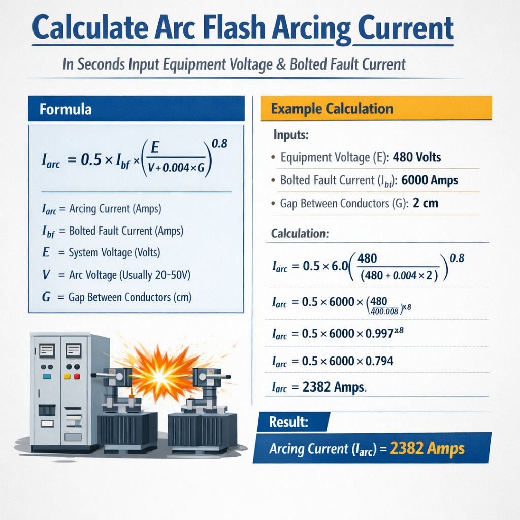
This article describes calculating arc flash arcing current from equipment voltage and bolted fault current.
Practical methods, formulas, examples, and standards compliance provided for engineers and safety professionals worldwide practice.Arc Flash Arcing Current Calculator (from Equipment Voltage and Bolted Fault Current)
Background and practical scope
Arc flash hazard assessment requires accurate estimation of the arcing current (Iarc) because incident energy and PPE categories depend primarily on the magnitude of that current and the arcing duration (seconds). This article focuses on how to derive arcing current from equipment voltage and bolted fault current, explains conservative approximations, and shows how the time (seconds) is used to translate arcing current into energy exposure.Content is oriented to low-voltage distribution and common industrial equipment (120 V through 600 V and typical medium-voltage switchgear). Where relevant the article references the empirical IEEE 1584 approach and highlights simplified engineering approximations suitable for preliminary calculations or validation of detailed models.Fundamental definitions and relationships
Bolted fault current (Ibf)
Bolted fault current is the theoretical symmetrical three-phase short-circuit current at the point of fault assuming no arcing impedance. For a three-phase system, the bolted fault current can be calculated from the equivalent source impedance Zs as:Ibf,3φ = VLL / (√3 × Zs)
Variables:- VLL — line-to-line nominal system voltage (volts).
- Zs — equivalent source impedance for the fault point (ohms).
- Ibf,3φ — three-phase bolted fault current (amperes).
Ibf,1φ = Vph / Zs
Arcing current (Iarc) and arcing impedance
Arcing current is the current that actually flows during an electrical arc event. The arc behaves as a non-linear impedance; its effective impedance is typically higher than a bolted fault but is strongly dependent on:- System voltage (V), line configuration (single-phase vs three-phase).
- Opening (electrode) gap and conductor geometry inside the equipment.
- Enclosure size and internal obstacles that influence plasma formation and cooling.
- Grounding method and fault type.
Iarc = R × Ibf
Variables:- Iarc — arcing current (amperes).
- R — arcing current ratio (dimensionless), empirically determined.
- Ibf — bolted fault current (amperes), as calculated above.
The IEEE 1584 empirical approach vs simplified ratio method
IEEE 1584 model (high accuracy)
IEEE 1584-2018 provides empirical equations derived from test data that compute arc current, arc power, and incident energy as functions of:- System voltage (V)
- Bolted fault current (Ibf)
- Enclosure type and dimensions
- Electrode gap
- Grounding (solid, resistive)
- Working distance
Simplified ratio method (engineering estimate)
For rapid assessments or sanity checks, the simplified formula below is commonly used:Iarc = R × Ibf
This method is conservative when R is selected from conservative tables calibrated from IEEE and field data. Use of R is acceptable for early-stage hazard screening and bench-checking of more sophisticated models.Typical arcing current ratios (R) for common equipment
Below are conservative typical R ranges drawn from IEEE industry guidance, peer-reviewed test summaries, and engineering practice. These are provided for engineering estimation only; specific project conditions may require IEEE 1584 calculations.| Equipment / Voltage class | Electrode gap small (≤ 8 mm) | Electrode gap medium (~9–25 mm) | Electrode gap large (>25 mm) | Open air (no enclosure) |
|---|---|---|---|---|
| 120–240 V low-voltage branch circuits | 0.30–0.60 | 0.25–0.50 | 0.20–0.40 | 0.60–0.95 |
| 208–480 V switchboards / breakers | 0.60–0.85 | 0.50–0.75 | 0.40–0.65 | 0.80–0.98 |
| 600 V motor/control centers | 0.65–0.90 | 0.55–0.80 | 0.45–0.70 | 0.85–1.00 |
| MV switchgear (1 kV–35 kV) — typical field | 0.75–0.95 | 0.65–0.90 | 0.60–0.85 | 0.90–1.10 |
- Values are ratios R = Iarc / Ibf. Use lower bound for conservative (smaller arc currents) or upper bound for worst-case arc currents depending on objective.
- Open-air arcs often approach bolted fault current due to minimal confinement losses; enclosed arcs typically reduce arcing current.
- Electrode gap is a critical variable—larger gaps increase arc impedance and reduce Iarc.
Formulas and variable explanations (HTML only)
Below are essential formula expressions written using only HTML elements and standard typography. Explanations and typical values are provided.Three-phase bolted fault current (symmetrical):
Ibf,3φ = VLL / (1.732 × Zs)
Variables:- VLL — line-to-line voltage (V). Typical values: 208, 480, 600 V.
- Zs — equivalent source impedance (ohms). Typical small industrial values: 0.002–0.02 Ω.
Single-phase bolted fault (phase-to-ground):
Ibf,1φ = Vph / Zs
Arcing current estimate (simplified):
Iarc = R × Ibf
Variables:- Iarc — arcing current (A).
- R — arcing current ratio, see tables above (dimensionless).
Working distance conversions (if needed):
Dm = Din × 0.0254
Variables:- Din — working distance in inches (typical 18 in = 0.4572 m).
- Dm — working distance in meters.
Simple proportional incident energy relationship (engineering approximation):
E ∝ Iarc2 × t
Explanation:- Where E is incident energy (arbitrary proportional units). This relation indicates incident energy scales approximately with square of arcing current and linearly with arc duration (seconds).
- For regulatory compliance use IEEE 1584 incident energy formulas or validated software; the proportional relation is useful for sensitivity analysis only.
Step-by-step calculation procedure
Follow this sequence to compute a conservative estimate of Iarc from voltage and bolted fault data:- Confirm system voltage and configuration (three-phase Y/Δ, single-phase). Record VLL or Vph.
- Obtain or calculate the equivalent source impedance Zs at the equipment. For transformer-supplied panels, include transformer impedance, feeder impedance, and utility contribution.
- Calculate bolted fault current:
- Three-phase: Ibf,3φ = VLL / (1.732 × Zs).
- Single-phase: Ibf,1φ = Vph / Zs.
- Select a conservative arcing ratio R based on equipment voltage, enclosure, and electrode gap (use table values or IEEE 1584 if available).
- Compute Iarc = R × Ibf.
- For incident energy sensitivity, apply E ∝ Iarc2 × t or preferably use IEEE 1584 to convert Iarc and t (seconds) into incident energy (cal/cm2).
Examples — worked calculations
Below are two complete, realistic examples. Each shows conversion of voltage and source impedance to bolted fault current, selection of R, calculation of Iarc, and basic discussion of how seconds (arc duration) affects energy.Example 1 — 480 V three-phase switchboard (industrial)
Problem statement:- System: 480 V three-phase, Y-connected distribution to switchboard.
- Equivalent source impedance at point of fault: Zs = 0.0055 Ω.
- Equipment: enclosed switchboard with medium electrode gap (~15 mm).
- Protective device clearing time for the worst case: t = 0.5 seconds (device fuse or breaker fault clearing).
- Working distance: 18 in (0.4572 m).
Ibf,3φ = VLL / (1.732 × Zs)
Substitute:Ibf,3φ = 480 / (1.732 × 0.0055)
Compute denominator:Ibf,3φ ≈ 480 / 0.009526 ≈ 50,393 A ≈ 50.4 kA
Step 2 — choose R from table:- For 480 V enclosed switchboard, medium gap, conservative R ≈ 0.7 (typical middle of range 0.50–0.75).
Iarc = R × Ibf = 0.70 × 50,393 ≈ 35,275 A ≈ 35.3 kA
Step 4 — interpret seconds (t) effect:- Using the proportional relation E ∝ Iarc2 × t, energy scales linearly with t. Doubling clearing time doubles incident energy.
- Relative energy baseline (arbitrary units): E ∝ (35.3)2 × 0.5 ≈ 624.6 × 0.5 ≈ 312.3 (kA2·s in arbitrary units).
- Iarc ≈ 35.3 kA is high; precise incident energy must be calculated with IEEE 1584 to determine PPE categories. This example shows the method from voltage and Zs to Iarc and how the time in seconds directly multiplies the energy exposure.
- Reducing clearing time (faster protection) or increasing R conservatively (selecting a smaller R if you want lower Iarc) affects the result—document choices.
Example 2 — 120/208 V three-phase motor control center (MCC)
Problem statement:- System: 208 V line-to-line, 120 V phase-to-neutral (wye) MCC feeding motors.
- Equivalent source impedance at MCC: Zs = 0.006 Ω for phase-to-ground faults.
- Equipment: enclosed MCC with small electrode gaps near contacts (~6 mm).
- Protective device clearing time t = 0.2 seconds (faster upstream breaker trip).
Vph = VLL / 1.732 = 208 / 1.732 ≈ 120 V
Step 2 — bolted fault current:Ibf,1φ = Vph / Zs = 120 / 0.006 = 20,000 A = 20 kA
Step 3 — choose R:- For 120–240 V MCC with small electrode gap, typical R ≈ 0.45 (range 0.30–0.60).
Iarc = 0.45 × 20,000 = 9,000 A = 9 kA
Step 5 — seconds (t) effect on relative energy:Relative E ∝ (9)2 × 0.2 = 81 × 0.2 = 16.2 (arbitrary units)
Discussion:- Iarc = 9 kA for this MCC scenario; the incident energy with t = 0.2 s will be significantly less than Example 1 because both Iarc and t are smaller.
- Still, precise E (cal/cm2) and PPE requirements must be derived from IEEE 1584 or approved software.
Tables of common values and device clearing times
This table lists common bolted fault currents for sample source impedances at representative voltages. Use as a quick reference when Zs is known.| VLL (V) | Zs (Ω) | Ibf,3φ (A) | Rounded (kA) |
|---|---|---|---|
| 480 | 0.002 | 480 / (1.732×0.002) ≈ 138,564 | 138.6 |
| 480 | 0.005 | 480 / (1.732×0.005) ≈ 55,425 | 55.4 |
| 480 | 0.010 | 480 / (1.732×0.010) ≈ 27,713 | 27.7 |
| 208 | 0.002 | 208 / (1.732×0.002) ≈ 60,048 | 60.0 |
| 208 | 0.006 | 208 / (1.732×0.006) ≈ 20,016 | 20.0 |
| 600 | 0.005 | 600 / (1.732×0.005) ≈ 69,282 | 69.3 |
| Device type | Typical worst-case clearing time (s) | Relative impact on E (linear factor) |
|---|---|---|
| Instantaneous fuses (small) | 0.01–0.05 | Very low |
| Fast-acting breakers | 0.03–0.2 | Low |
| Thermal-magnetic breakers | 0.1–0.6 | Moderate |
| Large distribution breakers / fuse-backup | 0.2–1.0+ | High |
| Failure to trip / remote clearing | >1.0 | Very high |
Validation, uncertainty, and practical recommendations
- For compliance-level arc flash studies, always use IEEE 1584-2018 methodology implemented in validated software or certified calculation tools. The R-based approach is only for rapid estimates or cross-checks.
- Document assumptions: source impedance, R value chosen, electrode gap, enclosure type, and protective device clearing time (seconds). Auditors and safety reviewers will require traceability.
- Conduct field measurements (short-circuit tests, impedance measurement) where practical to reduce uncertainty in Zs.
- Apply conservative assumptions for worker safety: if uncertain, use higher Iarc and longer clearing time to size PPE or engineering controls conservatively.
- Consider mitigation: faster fault clearing (reduces arc duration in seconds), current-limiting devices, arc-resistant switchgear, and remote racking to reduce worker exposure.
Standards, normative references, and further reading
The following standards and authority documents describe accepted methods, test procedures, and mandatory workplace requirements:- IEEE 1584-2018 — IEEE Guide for Performing Arc-Flash Hazard Calculations. (Primary empirical model for arcing current and incident energy.) https://standards.ieee.org/standard/1584-2018.html
- NFPA 70E — Standard for Electrical Safety in the Workplace. (Workplace safety requirements and PPE selection criteria.) https://www.nfpa.org/70E
- IEC 61482-1-1 — Live working — Protective clothing against the thermal hazards of an electric arc. (International garment testing standard.) https://www.iso.org/standard/62443.html (IEC store links via webstore.iec.ch)
- OSHA — Electrical Safety topics, including arc flash information. https://www.osha.gov/arc-flash
- IEEE PES publications and IEEE Xplore — for technical papers on arc modeling and field test data. https://ieeexplore.ieee.org
Practical checklist for implementing arcing current calculations
Use this checklist when preparing calculations or specifying protective measures:- Record nominal equipment voltage and configuration (VLL, delta/wye).
- Obtain Zs from system short-circuit study; measure if uncertain.
- Determine fault type (3φ, 1φ phase-to-ground) and use correct voltage for Ibf formula.
- Choose the method: IEEE 1584 (preferred) or ratio method (document R and rationale).
- Compute Iarc, document units and rounding.
- Apply arc duration (seconds) from protective device curves to estimate incident energy or use IEEE tools.
- Specify mitigation and PPE based on incident energy from validated calculations.
Limitations and cautions
- The R-ratio approach cannot substitute for IEEE 1584 where compliance or certification is required.
- Small differences in Zs lead to large changes in Ibf and thus Iarc because currents scale approximately with 1 / Zs. Verify impedances carefully.
- Arc behavior is stochastic; measured test values can vary. Use conservative engineering judgment and appropriate safety margins.
Summary of key actionable equations and definitions
- Three-phase bolted fault: Ibf,3φ = VLL / (1.732 × Zs)
- Single-phase bolted fault: Ibf,1φ = Vph / Zs
- Arcing current estimate: Iarc = R × Ibf (use IEEE 1584 when available)
- Incident energy sensitivity: E ∝ Iarc2 × t (qualitative scaling; use IEEE 1584 for numeric energy)