This guide explains converting circuit lists to kW, kVA, and amperes accurately for panel schedules.
Engineers, designers, and technicians use the instant calculator methodology for compliance and load balancing analysis.
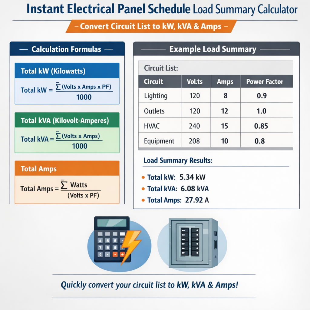
Instant Electrical Panel Load Summary – Convert Circuit List to kW, kVA and Amps
Purpose and scope of an instant panel schedule load summary calculator
An instant Electrical Panel Schedule Load Summary Calculator converts a detailed circuit list into consolidated electrical parameters: kilowatts (kW), kilovolt-amperes (kVA), and amperes (A). This process supports panel schedule creation, feeder sizing, breaker selection, and compliance verification. The calculator concept automates repeated arithmetic and enforces consistent application of power factor, demand, diversity, and code-required multipliers.
Core parameters and terminology
- Active power (P, in kW): Real power consumed by loads (lighting, motors, resistive heat).
- Apparent power (S, in kVA): Vector magnitude of total power including reactive component.
- Power factor (PF): Ratio P/S, often expressed as decimal (0.8 typical for motors, 0.95 for lighting).
- Voltage (V): Line-to-line voltage for three-phase systems (commonly 400 V, 480 V, 600 V), or line-to-neutral for single-phase.
- Current (I, in A): Electrical current required per circuit or feeder.
- Demand factor: Ratio applied to nameplate or connected load to reflect realistic simultaneous usage.
- Diversity factor: Aggregation reduction applied to groups of loads for sizing upstream equipment.
- Continuous load multiplier: Codes often require 125% of continuous loads for breaker sizing.
Essential formulas and variable definitions
Presenting formulas in plain HTML, then explaining variables and typical values used by calculators for accuracy.
For single-phase circuits:
For three-phase circuits (balanced):
Variable definitions and typical values
- VLL: Line-to-line voltage (e.g., 208 V, 400 V, 480 V). Typical North American three-phase is 480 V; European is often 400 V.
- V: Single-phase voltage (e.g., 120 V, 230 V).
- PF: Power factor. Typical values: lighting (0.9–0.99), small motors (0.8–0.9 uncorrected), large motors (0.85–0.95 with correction).
- √3: Square root of three ≈ 1.732.
- Continuous load multiplier: 1.25 (NEC requirement for breaker sizing on continuous loads greater than three hours).
Step-by-step procedure to convert a circuit list to kW, kVA, and amps
- Collect circuit nameplate data: voltage, rated current, power in watts or amps, PF if given, and phase (1Ø or 3Ø).
- Normalize units: convert watts to kW (divide by 1000), convert VA to kVA (divide by 1000).
- If only amperes are provided for a given voltage, compute kW using formulas above and assumed PF if not specified.
- Apply demand or diversity factors per code or engineering rules for groups of loads (e.g., receptacle loads, lighting, HVAC).
- Sum kW and kVA per panel and per phase; compute feeder currents using three-phase formulas where appropriate.
- Check balancing across phases: report maximum phase current and identify phase imbalances.
- Apply safety multipliers for continuous loads and required breaker sizing (e.g., ×1.25), then select conductor ampacity and breaker rating.
- Document results in the panel schedule: circuit ID, load description, kW, kVA, power factor, phase, breaker size, and comments (continuous, motor, AFCI, etc.).
Common conversions and lookup tables
| Typical Load Type | Typical Power (W) | Typical PF | P (kW) | S (kVA) |
|---|---|---|---|---|
| Residential general lighting (per circuit) | 1200 | 0.95 | 1.2 | 1.263 |
| Small appliance / receptacle branch | 1800 | 0.9 | 1.8 | 2.0 |
| Office workstation (PC + monitor) | 300 | 0.95 | 0.3 | 0.316 |
| Server rack (per rack) | 2500 | 0.9 | 2.5 | 2.778 |
| Single-phase HVAC condenser (split-system) | 3500 | 0.9 | 3.5 | 3.889 |
| Three-phase small motor (3–10 HP) | Variable | 0.85 | See notes | See notes |
| Voltage System | Formula for I (A) from P (kW) | Example: P = 5 kW, PF = 0.9 |
|---|---|---|
| Single-phase 230 V | I = (P×1000) / (V × PF) | I = (5×1000) / (230 × 0.9) = 24.13 A |
| Three-phase 400 V | I = (P×1000) / (√3 × V × PF) | I = (5×1000) / (1.732 × 400 × 0.9) = 8.01 A |
| Three-phase 480 V | I = (P×1000) / (√3 × V × PF) | I = (5×1000) / (1.732 × 480 × 0.9) = 6.68 A |
| Breaker Ampere Rating (A) | Typical Max Continuous Load Allowed (A) | Typical conductor AWG (Cu) Ampacity |
|---|---|---|
| 15 | 12 (15 × 0.8) | 14 AWG (20 A rated) |
| 20 | 16 | 12 AWG (25–30 A rated depending on insulation) |
| 30 | 24 | 10 AWG (35–40 A) |
| 60 | 48 | 6 AWG (65–75 A depending on conditions) |
| 100 | 80 | 3 AWG (100 A typical) |
Applying demand and diversity factors
Accurate panel scheduling uses demand and diversity to reduce connected loads to realistic feeder and service requirements. Typical examples include:
- Lighting: often 100% connected, but some jurisdictions allow demand factors per area or final circuit counts.
- Receptacles: apply demand factors per code (e.g., NEC Table 220.55 for dwelling unit receptacle loads).
- Motors: evaluate starting currents, duty cycle, and coincidence; sum full-load kW for continuous warming, but use diversity for large fleets of intermittent motors.
- HVAC: large central HVAC often requires diversity when not all units run simultaneously, but code may require maximum demand consideration for service size.
Example demand factors (typical)
- General lighting: 100% considered but sometimes reduced with luminaire diversity for large installations.
- Small appliance circuits: NEC rules for kitchen receptacles apply specific demand assumptions.
- Commercial office receptacles: 100% connected, apply reduction at service level per load schedule.
Real-case Example 1: Small commercial panel schedule (step-by-step)
Scenario: A small office panel with 12 circuits: 6 lighting, 4 general receptacles, 1 server rack, 1 HVAC single-phase condenser. Objective: Convert circuit list into kW, kVA, and amps; size breakers and report panel summary.
Circuit list and given nameplate data
- Lighting circuit L1: 1200 W, single-phase 230 V, PF 0.95
- Lighting circuit L2: 1200 W, single-phase 230 V, PF 0.95
- Lighting circuit L3: 1200 W, single-phase 230 V, PF 0.95
- Lighting circuit L4: 1200 W, single-phase 230 V, PF 0.95
- Lighting circuit L5: 1200 W, single-phase 230 V, PF 0.95
- Lighting circuit L6: 1200 W, single-phase 230 V, PF 0.95
- Receptacle circuit R1: 1800 W, single-phase 230 V, PF 0.9
- Receptacle circuit R2: 1800 W, single-phase 230 V, PF 0.9
- Receptacle circuit R3: 1800 W, single-phase 230 V, PF 0.9
- Receptacle circuit R4: 1800 W, single-phase 230 V, PF 0.9
- Server rack SR1: 2500 W, single-phase 230 V, PF 0.95
- HVAC condenser HVAC1: 3500 W, single-phase 230 V, PF 0.9 (non-continuous)
Step 1: Convert W to kW and compute kVA
Compute for each circuit using formulas above. Show representative calculations for L1 and SR1, then sum.
Step 2: Tabulate all circuits (summation)
Totals:
- Total lighting P = 6 × 1.2 kW = 7.2 kW; Slighting = 6 × 1.263 = 7.578 kVA
- Total receptacles P = 4 × 1.8 kW = 7.2 kW; Srec = 4 × 2.0 = 8.0 kVA (approx)
- Server P = 2.5 kW; Sserver = 2.632 kVA
- HVAC P = 3.5 kW; S HVAC = 3.889 kVA
- Grand total Pconnected = 7.2 + 7.2 + 2.5 + 3.5 = 20.4 kW
- Grand total Sconnected ≈ 7.578 + 8.0 + 2.632 + 3.889 = 22.099 kVA
Step 3: Apply demand factors and continuous load rules
If local code allows a 75% demand for general receptacles (example policy), apply:
- Adjusted receptacle P = 7.2 × 0.75 = 5.4 kW
- Lighting generally taken at 100% → 7.2 kW
Step 4: Compute feeder current (single-phase service assumed at 230 V)
Ifeeder = (P × 1000) / (V × PF_system). Assume overall PF ~ 0.92 (weighted estimate).
Step 5: Panel and conductor sizing
- Continuous loads: Identify continuous sections (lighting may be continuous). If lighting is continuous, its portion = 7.2 kW → current lighting = (7.2×1000)/(230×0.95)=32.83 A. Apply 125% multiplier for breaker sizing on continuous portion as required → 32.83×1.25 = 41.0 A required for lighting protection.
- Select main breaker and feeder: Because total calculated feeder current is ~87.9 A, choose a 100 A panel and conductors sized per ampacity tables (e.g., 3 AWG Cu for 100 A typical) with appropriate derating.
Resulting schedule summary (abbreviated)
- Total connected: 20.4 kW (22.1 kVA)
- After demand: 18.6 kW (~20.22 kVA at PF 0.92)
- Calculated feeder current: 87.9 A → select 100 A breaker and conductor (verify local ampacity)
Real-case Example 2: Three-phase industrial panel with motors
Scenario: A three-phase distribution panel serving 4 motors (5 HP, 10 HP, 20 HP, 30 HP), lighting, and miscellaneous resistive loads. Objective: compute kW, kVA, and amps per circuit, apply motor starting considerations and diversity, then size feeder.
Nameplate data and assumptions
- Voltage: 480 V three-phase (VLL)
- Motors: use full-load kW based on HP to kW conversion: 1 HP = 0.746 kW.
- PF for motors: assume 0.85 at full load.
- Lighting: 4 kW total, PF 0.95 (three-phase balanced across phases).
- Misc resistive: 6 kW total (heaters), PF = 1.0.
Step 1: Motor power conversion
- Motor M1: 5 HP → P = 5 × 0.746 = 3.73 kW; S = 3.73 / 0.85 = 4.388 kVA
- Motor M2: 10 HP → P = 7.46 kW; S = 8.776 kVA
- Motor M3: 20 HP → P = 14.92 kW; S = 17.553 kVA
- Motor M4: 30 HP → P = 22.38 kW; S = 26.329 kVA
Step 2: Sum connected loads
- Total motors P = 3.73 + 7.46 + 14.92 + 22.38 = 48.49 kW
- S_motors = 4.388 + 8.776 + 17.553 + 26.329 = 56. + approx 56. ; precise 56. + rounding → 56. ... (sum = 56. + )
- Lighting P = 4.0 kW (S ≈ 4.21 kVA)
- Resistive P = 6.0 kW (S = 6.0 kVA)
- Grand total Pconnected = 48.49 + 4 + 6 = 58.49 kW
Step 3: Apply motor diversity and demand
Industrial practice often applies diversity to motors not expected to run simultaneously, or uses a demand factor table (e.g., 85–100% for small sets, lower for large sets). For this example, assume 90% coincidence for motors.
- Adjusted motor P = 48.49 × 0.9 = 43.641 kW
- Total adjusted P = 43.641 + 4 + 6 = 53.641 kW
Step 4: Compute feeder current for three-phase 480 V and PF ≈ weighted 0.88
Step 5: Motor starting and short-term capacity
- Verify starter rating and bus transient capacity. Large motors have locked-rotor currents (LRA) several times full-load current; ensure soft-starters, VFDs, or reduced-voltage starters where bus voltage drop or supply stability is a concern.
- Full-load currents per motor (approx): compute each motor current I = (P×1000)/(√3×480×PF).
Example M4 current: I = (22.38×1000)/(1.732×480×0.85) = 31.5 A (full load). LRA may be 5–7× → 157–220 A starting requirement (short duration)
Step 6: Panel and conductor selection
- Calculated steady-state feeder current ~73.2 A → select 100 A feeder breaker to allow margin and code-required continuous multipliers when needed.
- Assess voltage-drop for long feeders: ensure conductor sizing meets max voltage drop criteria (commonly ≤3% feeder).
Phase balancing, neutral currents, and harmonic considerations
Accurate panels require phase-level distribution to minimize neutral currents and harmonic distortion. For three-phase loads, assign single-phase circuits across phases in a rotating pattern (A, B, C, A, B, C) to balance kW across phases.
- Neutral current calculation for single-phase circuits: In unbalanced systems, neutral current is the vector sum of phase currents. Provide programmatic summation rather than scalar.
- Harmonics: Non-linear loads (VFDs, servers) generate triplen and other harmonics which can increase neutral heating and require derated conductors or harmonic filters. Evaluate total harmonic distortion (THD) per IEEE 519 guidelines.
Panel schedule output format and export considerations
Instant calculators should export results in a structured panel schedule format, including fields:
- Circuit ID
- Load description
- Phase designation
- kW and kVA per circuit
- Power factor
- Breaker size
- Continuous status
- Notes (demand factor applied, starting requirements)
Data should be exportable to CSV, Excel, and PDF for integration with BIM and electrical design tools (Revit schedules, ETAP, SKM PowerTools).
Regulatory references and authoritative sources
Designers must align calculators and outputs with recognized standards and codes. Key normative references:
- NEC (NFPA 70) — National Electrical Code. Official resource: https://www.nfpa.org/NEC
- IEC 60364 — Electrical installations of buildings. Official IEC site: https://www.iec.ch/
- IEEE Std 141 (Red Book) — Power distribution reference for industrial plants. IEEE: https://standards.ieee.org/
- IEEE Std 519 — Recommended practices for harmonic control. Details at IEEE Xplore: https://ieeexplore.ieee.org/
- NEMA standards for equipment and motor performance: https://www.nema.org/
Accuracy checks and verification steps
- Cross-check arithmetic sums between kW total and phase currents calculated from kW.
- Ensure PF assumptions are conservative; where unknown, measure or default to 0.9 for typical mixed loads.
- Verify continuous load identification and apply the 125% rule for breaker sizing as required by NEC section on continuous loads.
- Validate final selections against conductor ampacity tables, temperature correction factors, and bundling derating where conductors run in trays or conduits.
- Perform voltage-drop verification for feeders and branch circuits over length with chosen conductor sizes.
Implementation tips for an instant calculator algorithm
- Input normalization: accept W, kW, VA, kVA, A with explicit voltage and phase; convert internally to standard units (kW and kVA).
- PF handling: allow explicit PF input per circuit; provide default PF presets by load category.
- Demand factor library: include tables by jurisdiction and load type with override capability for engineering judgment.
- Continuous load flag: boolean per circuit to automatically apply 1.25 multiplier for downstream protective device sizing.
- Phase assignment optimizer: algorithmically distribute single-phase circuits across three phases to minimize imbalance metric (e.g., minimize max phase current variance).
- Report generation: create detailed per-circuit breakdown and summarized feeder/panel outputs with traceability to input assumptions.
Testing and validation
Validate the calculator against manual hand calculations and industry-standard tools. Unit tests should include:
- Single-phase conversions with various PFs
- Three-phase motor banks with diversity application
- Phase balancing scenarios with intentionally unbalanced inputs
- Harmonic-rich loads with THD impact on neutral currents (if harmonics module included)
Operational recommendations and maintenance
- Periodically update demand and diversity tables to reflect latest codes and measured building utilization patterns.
- Include audit logs for each calculated panel schedule with timestamps, user, and input dataset to support project QA/QC.
- Maintain links to normative references and evidence of compliance decisions in project documentation.
Further reading and authoritative links
- NFPA 70 (NEC) online resources and subscription options: https://www.nfpa.org/NEC
- IEC standards catalog (IEC 60364 and related): https://www.iec.ch/
- IEEE standards library (IEEE 519 for harmonics, IEEE 141 for distribution): https://standards.ieee.org/
- NEMA motor and enclosure standards: https://www.nema.org/
- Energy efficiency and power factor correction guidance from reputable engineering societies (CIBSE, ASHRAE) — ASHRAE: https://www.ashrae.org/
Key takeaways for using the instant calculator effectively
- Always capture accurate input: voltage, phase, PF, load type, and continuous duty.
- Document assumptions: demand factors, diversity rules, and correction multipliers.
- Run phase balancing and verify neutral current in mixed single- and three-phase installations.
- Use code-required multipliers for continuous loads and apply conservative PFs where uncertainty exists.
- Integrate the calculator output into panel schedules, protective device selection, and conductor sizing workflows.
Appendix: Quick reference formulas and constants
| Formula | Description | Constant / Typical Value |
|---|---|---|
| P(kW) = (V × I × PF) / 1000 | Single-phase active power | V: 230 V common; PF: 0.9–0.95 typical |
| P(kW) = (√3 × V × I × PF) / 1000 | Three-phase active power (balanced) | √3 ≈ 1.732; VLL: 400–480 V common |
| I(A) = (P × 1000) / (V × PF) | Single-phase current from power | Use PF default 0.9 when unknown |
| I(A) = (P × 1000) / (√3 × V × PF) | Three-phase current from power | Derate by temperature and bundling separately |
| S(kVA) = P(kW) / PF | Apparent power from active power | PF must be > 0.0; typical 0.85–0.98 |
- NFPA 70: National Electrical Code — https://www.nfpa.org/NEC
- IEC 60364: Electrical Installations of Buildings — https://www.iec.ch/
- IEEE Std 519-2014: Recommended Practice and Requirements for Harmonic Control — https://standards.ieee.org/
- IEEE Std 141: Recommended Practice for Electric Power Distribution for Industrial Plants — https://standards.ieee.org/
- NEMA standards and motor guidance — https://www.nema.org/