Accurate transformer fault currents require precise conversion of kVA, voltage, and impedance values for equipment.
This technical article supplies methods, formulas, examples, and normative references for reliable calculations in practice.
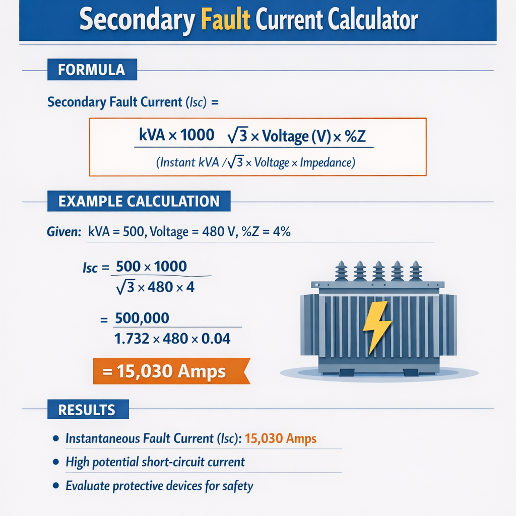
Transformer Secondary Fault Current Calculator (Instantaneous kA from kVA, Voltage and %Z)
Fundamental principles for transformer secondary fault current calculation
Transformer short-circuit (fault) current on the secondary is determined by the transformer's rated apparent power (kVA or MVA), the nominal secondary voltage, and the transformer's short-circuit impedance (Z% on the nameplate). The steady-state symmetrical short-circuit current at the secondary terminals can be calculated directly using nameplate kVA and percent impedance (Z%). This section sets the analytical basis and the frequently used algebraic relationships for quick, accurate calculations and for implementing an automated calculator.Key assumptions, scope, and applicability
- Balanced three-phase bolted faults at the secondary terminals (phase-to-phase or phase-to-ground symmetrical RMS values). - Transformer nameplate provides percent impedance (Z%), rated kVA, and rated primary/secondary voltages. - Source system impedance and other series impedances can be included separately; basic formulas assume transformer impedance dominates when calculating short-circuit contribution at the secondary. - Results presented are steady-state symmetrical RMS values unless a peak/instantaneous factor is applied (see transient/peak section).Fundamental formulas and variable definitions
Use only the transformer nameplate values and standard electrical relationships. Formulas below use HTML characters; explanations of each variable and typical values follow.For three-phase systems:
I_rated = S_kVA × 1000 / (sqrt(3) × V_ll)
Z_pu = Z_percent / 100
I_sc_sym = I_rated / Z_pu
Short-circuit MVA (symmetrical) at secondary: MVA_sc = S_MVA / Z_pu
For single-phase systems:
I_rated_1ph = S_kVA × 1000 / V
I_sc_1ph = I_rated_1ph / Z_pu
- S_kVA — transformer rated apparent power in kilovolt-amperes (kVA). Typical values: 25, 50, 150, 500, 1500 kVA.
- S_MVA — transformer rated apparent power in megavolt-amperes (MVA) where S_MVA = S_kVA / 1000.
- V_ll — line-to-line nominal secondary voltage in volts (V) for three-phase. Typical LV values: 480 V, 400 V, 4160 V, 4160 V, 6900 V.
- V — phase voltage for single-phase or phase-to-neutral calculation.
- Z_percent — percent impedance on the transformer nameplate (Z%). Typical manufacturer values: 2.5%, 4.0%, 5.75%, 6.0%, 8.0%.
- Z_pu — per-unit impedance = Z_percent / 100.
- I_rated — rated current in amperes at rated kVA and voltage.
- I_sc_sym — symmetrical RMS short-circuit current in amperes (steady-state) at the transformer's secondary terminals considering only the transformer's own impedance.
- MVA_sc — short-circuit power in MVA available at the transformer secondary terminals (symmetrical).
- sqrt(3) ≈ 1.73205080757.
- Common Z_percent values: 5.75% for many distribution transformers, 4.0% for low-impedance units, 8.0% for high-impedance designs.
- Transformer rated currents vary strongly with kVA and voltage; see table below for computed values and resulting short-circuit currents for common combinations.
Extensive tables of common kVA, voltage, impedance and fault results
| kVA | Secondary V (LL) | Z% | Rated Current (A) | Symmetric I_sc (A) | Short-circuit MVA |
|---|---|---|---|---|---|
| 25 | 480 | 5.75 | 30.1 | 523 | 0.025 / 0.0575 = 0.434 |
| 50 | 480 | 5.75 | 60.2 | 1046 | 0.05 / 0.0575 = 0.870 |
| 150 | 480 | 5.75 | 180.4 | 3139 | 0.150 / 0.0575 = 2.609 |
| 300 | 480 | 4.00 | 360.8 | 9020 | 0.300 / 0.04 = 7.500 |
| 500 | 480 | 4.00 | 601.0 | 15025 | 0.500 / 0.04 = 12.50 |
| 750 | 480 | 5.75 | 901.5 | 15675 | 0.750 / 0.0575 = 13.04 |
| 1000 | 480 | 5.75 | 1202.1 | 20934 | 1.000 / 0.0575 = 17.39 |
| 1500 | 480 | 5.75 | 1803.2 | 31386 | 1.500 / 0.0575 = 26.09 |
| 2000 | 480 | 8.00 | 2404.2 | 30053 | 2.000 / 0.08 = 25.00 |
| 2500 | 480 | 8.00 | 3005.3 | 37566 | 2.500 / 0.08 = 31.25 |
| kVA | Secondary V (LL) | Z% | Rated Current (A) | Symmetric I_sc (A) | Short-circuit MVA |
|---|---|---|---|---|---|
| 500 | 4160 | 6.0 | 69.4 | 1156 | 0.500 / 0.06 = 8.333 |
| 750 | 4160 | 6.0 | 104.1 | 1734 | 0.750 / 0.06 = 12.50 |
| 1000 | 4160 | 6.0 | 138.8 | 2312 | 1.000 / 0.06 = 16.67 |
| 1500 | 4160 | 5.0 | 208.2 | 4164 | 1.500 / 0.05 = 30.00 |
| 2000 | 4160 | 5.0 | 277.6 | 5552 | 2.000 / 0.05 = 40.00 |
| 3000 | 4160 | 7.0 | 416.4 | 5949 | 3.000 / 0.07 = 42.86 |
- Rated Current (A) is computed by the equation I_rated = S_kVA*1000 / (sqrt(3) × V).
- Symmetric I_sc (A) is computed as I_rated / (Z%/100).
- Short-circuit MVA is computed as S_MVA / Z_pu = (S_kVA/1000) / (Z%/100).
Accounting for source impedance and combined systems
Transformers do not operate in isolation. The available short-circuit current at the transformer secondary is affected by the upstream source short-circuit impedance (utility or generator). Use per-unit or impedance summation to include both contributions. Formulas:Z_total_pu = Z_transformer_pu + Z_source_pu
I_sc_total = I_base / Z_total_pu
- I_base (per unit base) = 1 pu corresponds to I_rated.
- Alternate direct method: Compute transformer's contribution I_tr and source's short-circuit MVA (S_sc_source). Convert S_sc_source to an equivalent per-unit impedance on the transformer MVA base: Z_source_pu_on_Sbase = S_MVA_base / S_sc_source.
- Choose a common MVA base (typically the transformer's MVA rating).
- Compute Z_transformer_pu = Z%/100.
- Obtain system short-circuit MVA from utility or compute source impedance; convert to Z_source_pu_on_base = S_MVA_base / S_sc_source.
- Compute Z_total_pu = Z_transformer_pu + Z_source_pu_on_base.
- Compute I_sc_total = S_MVA_base / (sqrt(3) × V_secondary) / Z_total_pu or equivalently I_rated / Z_total_pu.
- If utility S_sc = 100 MVA at the transformer's secondary base is known, and transformer S_MVA = 1.5 MVA, then Z_source_pu_on_base = 1.5 / 100 = 0.015 pu.
- With Z_transformer_pu = 0.0575 pu, Z_total_pu = 0.0725 pu and I_sc_total = I_rated / 0.0725.
Peak and instantaneous current considerations (transient, DC-offset)
The preceding calculations produce the steady-state symmetrical RMS short-circuit current. Protection device selection (breakers, fuses, relay settings) and mechanical stresses require knowledge of the maximum instantaneous peak (asymmetrical) current during the first cycle after fault inception. Standards (IEC 60909 and IEEE C37.010) provide methods to determine peak factors including DC offset and X/R dependency. Key points:- IEC 60909 specifies a peak factor k that depends on R/X and the system parameters for converting initial symmetrical RMS current to first-peak asymmetrical current.
- Conservative engineering practice often uses a peak factor between 2.0 and 2.6 for transformer low-voltage bolted faults where X/R is moderate and worst-case point-on-wave initiation is assumed.
I_peak ≈ k_peak × I_sc_sym
Typical k_peak values (illustrative; consult IEC 60909 and IEEE for rigorous calculation):- Low X/R (<1): k_peak ≈ 1.8–2.0
- Moderate X/R (1–5): k_peak ≈ 2.0–2.4
- High X/R (>5): k_peak may exceed 2.4 and approach 3.0 for extreme cases
Worked examples — complete step-by-step solutions
Example 1 — Three-phase 1500 kVA, 480 V secondary, Z% = 5.75%
Given:- S_kVA = 1500 kVA
- V_secondary (V_ll) = 480 V
- Z% = 5.75%
I_rated = S_kVA × 1000 / (sqrt(3) × V)
I_rated = 1500 × 1000 / (1.73205 × 480) = 1,500,000 / 831.38 = 1803.2 A
Z_pu = 5.75 / 100 = 0.0575 pu
I_sc_sym = I_rated / Z_pu = 1803.2 / 0.0575 = 31,356 A ≈ 31.36 kA
MVA_sc = S_MVA / Z_pu = (1500 / 1000) / 0.0575 = 1.5 / 0.0575 = 26.087 MVA
I_peak ≈ 2.2 × 31.36 kA ≈ 68.99 kA
Summary of results:- Rated current: 1,803 A
- Symmetric RMS short-circuit current at secondary: ≈ 31.36 kA
- Short-circuit MVA: ≈ 26.09 MVA
- Estimated first-peak instantaneous current (conservative): ≈ 69.0 kA
Example 2 — Single-phase 250 kVA, 240 V, Z% = 6.0%
Given:- S_kVA = 250 kVA (single-phase)
- V = 240 V
- Z% = 6.0%
I_rated_1ph = S_kVA × 1000 / V = 250 × 1000 / 240 = 250,000 / 240 = 1,041.67 A
Step 2 — Convert percent impedance to per unit:Z_pu = 6.0 / 100 = 0.06 pu
I_sc_1ph = I_rated_1ph / Z_pu = 1,041.67 / 0.06 = 17,361 A ≈ 17.36 kA
I_peak ≈ 2.0 × 17.36 kA = 34.72 kA
- Single-phase rated current: 1,041.7 A
- Symmetric RMS short-circuit current: ≈ 17.36 kA
- Estimated first-peak instantaneous current: ≈ 34.7 kA
Example 3 — Including upstream source impedance (practical combined calculation)
Given:- Transformer: 500 kVA, 480 V secondary, Z% = 4.0% → Z_tr = 0.04 pu
- Utility specified fault level at transformer secondary: S_sc_source = 100 MVA (three-phase)
Z_source_pu_on_base = S_MVA_base / S_sc_source = 0.5 / 100 = 0.005 pu
Z_total_pu = Z_tr + Z_source = 0.04 + 0.005 = 0.045 pu
I_rated = 500 × 1000 / (1.732 × 480) = 601.0 A
I_sc_total = I_rated / Z_total_pu = 601.0 / 0.045 = 13,355 A ≈ 13.36 kA
Best practices for measurement, verification and protection coordination
- Always verify nameplate data: kVA rating, rated voltages, and percent impedance (Z%). Percent impedance can differ between units of the same design — use the actual unit data.
- Where possible, request system short-circuit data from the utility. The utility typically provides prospective fault MVA at customer connection points.
- For protective device selection, consider both symmetrical RMS and first-peak asymmetrical currents. Use standards (IEC 60909, IEEE C37.010) for formal peak calculations.
- Consider inrush currents, energization transients, and the effect of parallel transformers or transformer banks when performing coordination studies.
- Document all assumptions (Z% used, MVA bases, X/R ratios) to enable later verification and audits.
Normative references and further reading
- IEC 60909 — Short-circuit current calculations in three-phase AC systems: https://www.iec.ch/standards/60909 (standard for fault current calculation methodologies under IEC rules).
- IEC 60076 — Power transformers: https://www.iec.ch/standards/60076 (covering transformer testing and impedance definitions).
- IEEE Std C37.010 — IEEE Application Guide for AC High-Voltage Circuit Breakers Rated on a Symmetrical Current Basis: https://standards.ieee.org/ (Search for C37.010 for current application guidance and peak factor methods).
- IEEE Std 141 (IEEE Red Book) and IEEE Std 399 (Brown Book) — power system analysis references for fault calculation and coordination.
- ANSI/NEMA C57 series — Distribution and power transformer standards and test protocols: https://www.nema.org/standards.
Summary of actionable calculation steps for an automated calculator
For a reliable transformer secondary fault current calculator, implement the following flow:- Input: S_kVA, V_secondary (LL), Z_percent, system fault MVA (optional), transformer winding configuration (single/three-phase).
- Compute I_rated using the formula for three-phase or single-phase as appropriate.
- Compute Z_pu = Z_percent/100.
- If system fault MVA provided, convert to Z_source_pu_on_base and compute Z_total_pu = Z_pu + Z_source_pu.
- Compute steady-state symmetrical RMS short-circuit current: I_sc = I_rated / Z_total_pu.
- If required, compute short-circuit MVA on the MVA base: MVA_sc = S_MVA / Z_total_pu.
- Optionally apply peak factor (per IEC/IEEE methods) to compute first-peak instantaneous current for mechanical and interruption stress calculations.
- Output: I_rated (A), I_sc_sym (A), I_peak (A, optional), MVA_sc, and documentation of assumptions.
Final technical considerations and cautions
- Percent impedance tolerance: manufacturing tolerances can lead to variations; where critical, perform factory or field impedance tests (short-circuit ratio tests) to confirm.
- Parallel transformers: when transformers operate in parallel, combined impedance calculation must include phase shift, vector group compatibility, and proportional sharing based on impedances.
- Ground faults and unbalanced conditions require sequence-network analysis; the simple symmetric formulas apply only to balanced three-phase faults.
- Protections should be coordinated based on the lowest expected fault currents for sensitivity and the highest potential peak currents for interrupting capacity.