Electrical substations and power plants must protect personnel from dangerous step and touch voltage hazards. IEEE 80 and IEC 60479 define limits, ensuring grounding grids prevent hazardous shocks during faults.
Step & Touch Voltage — IEEE 80 / IEC Calculator
Compute allowable step and touch voltages (safety limits) and estimate actual voltages. Based on IEEE Std. 80 and IEC 60479 methodology.
What this calculator gives
Formulas used
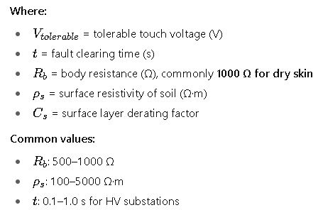
– Allowable body current (Ib): Ib = k / sqrt(t), where k = 0.157 for 70 kg, 0.116 for 50 kg (t in seconds).
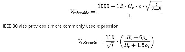
– Touch limit: Etouch_limit = Ib · (Rb + 3.125 · ρs · Cs) (Rb = 1000 Ω).
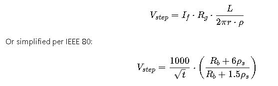
– Step limit: Estep_limit = Ib · (Rb + 6.25 · ρs · Cs).
IEC: uses heart-current & body impedance method (IEC 60479) — calculator maps IEC by applying IEC body factor and heart-current factor when selected.
References
Fundamentals of Step and Touch Voltage
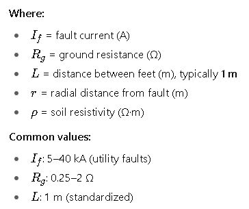
- Step Voltage (Vs): The potential difference between a person’s feet spaced 1 m apart when standing on the ground near a fault current dissipation.
- Touch Voltage (Vt): The potential difference between a grounded structure (such as a substation fence or equipment) and a point on the ground where a person is standing.
Both values must remain below permissible limits to prevent ventricular fibrillation, muscle contraction, or thermal injury as per IEC and IEEE thresholds.
Extensive Tables of Common Step and Touch Voltage Limits
The following tables compile the most referenced permissible limits based on IEEE Std. 80 and IEC 60479, considering body weight, fault clearing time, and soil resistivity.
Table 1 – Tolerable Touch Voltage (IEEE 80, IEC 60479)
| Body Weight (kg) | Fault Clearing Time (s) | Tolerable Touch Voltage (V) – IEEE 80 | Tolerable Touch Voltage (V) – IEC |
|---|---|---|---|
| 50 | 0.1 | 785 | 430 |
| 50 | 0.5 | 351 | 200 |
| 50 | 1.0 | 247 | 140 |
| 70 | 0.1 | 1000 | 500 |
| 70 | 0.5 | 443 | 250 |
| 70 | 1.0 | 310 | 165 |
| 100 | 0.1 | 1200 | 600 |
| 100 | 0.5 | 532 | 300 |
| 100 | 1.0 | 373 | 200 |
Table 2 – Tolerable Step Voltage (IEEE 80, IEC 60479)
| Body Weight (kg) | Fault Clearing Time (s) | Tolerable Step Voltage (V) – IEEE 80 | Tolerable Step Voltage (V) – IEC |
|---|---|---|---|
| 50 | 0.1 | 1570 | 870 |
| 50 | 0.5 | 700 | 400 |
| 50 | 1.0 | 495 | 280 |
| 70 | 0.1 | 2000 | 1000 |
| 70 | 0.5 | 885 | 500 |
| 70 | 1.0 | 620 | 330 |
| 100 | 0.1 | 2400 | 1200 |
| 100 | 0.5 | 1060 | 600 |
| 100 | 1.0 | 745 | 400 |
These values are derived using body impedance models and fault duration tolerances provided in IEEE 80 and IEC 60479. They are widely used in grounding design software and calculators.
Step and Touch Voltage Formulas (IEEE Std. 80-2013)
1. Tolerable Touch Voltage Formula
2. Step Voltage Formula
3. Ground Potential Rise (GPR)
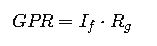
This represents the maximum rise in potential of a grounded system during fault conditions.
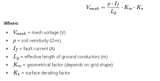
4. Mesh Voltage (Worst Case Touch Voltage in a Substation Grid)
5. Step Voltage in Substation Grid
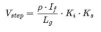
Where Ki is the step voltage geometrical factor.
These formulas are implemented in commercial software like ETAP Ground Grid, CDEGS, and SKM Power Tools, but can also be applied in Excel or Python calculators.
Real-World Application Examples
Example 1 – Substation Grounding System (IEEE 80 Method)
Problem Statement:
A 132 kV substation experiences a 10 kA single-line-to-ground fault. Soil resistivity is 100 Ω·m, ground resistance 0.5 Ω, and clearing time 0.5 s. Calculate whether the step and touch voltages are within safe limits.
Solution:
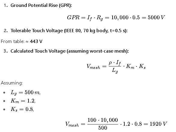
Since 1920 V > 443 V, the design is unsafe.
Mitigation:
- Increase grid conductor density
- Add crushed rock surface (ρs ↑)
- Install deep ground rods
Example 2 – Wind Farm Collector Substation (IEC 60479)
Problem Statement:
A 220/34.5 kV wind farm substation with 7 kA fault current, soil resistivity = 300 Ω·m, and clearing time = 1.0 s. Check compliance with IEC tolerable voltages.
Solution:
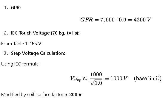
Result:
- Touch voltage ≈ 600 V > 165 V → Unsafe
- Step voltage ≈ 800 V < 1000 V → Safe
Mitigation:
- Add geotextile + gravel to raise surface resistivity
- Extend grounding grid to lower mesh voltage
Comparison Between IEEE 80 and IEC 60479 Methodologies
Although both IEEE 80 and IEC 60479 aim to safeguard human life from electric shock hazards, their methodologies differ in certain assumptions:
- IEEE 80
- Assumes body weight of 50 kg and 70 kg as reference.
- Uses a body resistance of 1000 Ω for dry conditions and 500 Ω for wet conditions.
- Considers the fault clearing time as a critical factor.
- Widely applied in North America, Latin America, and Asia.
- IEC 60479
- Defines several zones of current effects on the human body (zones 1–4).
- Uses safety curves for duration versus current thresholds.
- Tends to be more conservative than IEEE, especially for touch voltage limits.
- Commonly applied in Europe, Africa, and parts of the Middle East.
For international projects, engineers often evaluate grounding systems against both standards to ensure compliance with the strictest limits.
Extended Reference Tables for Design Parameters
Table 3 – Typical Soil Resistivity Values
| Soil Type | Resistivity (Ω·m) |
|---|---|
| Saturated clay | 10 – 50 |
| Loam soil | 50 – 200 |
| Sand | 200 – 1000 |
| Gravel | 1000 – 3000 |
| Bedrock (granite) | 3000 – 10,000 |
| Dry desert soil | > 20,000 |
Table 4 – Human Body Resistance Values (IEC and IEEE Reference)
| Condition | Resistance (Ω) |
|---|---|
| Dry skin, hand-to-hand | 1000 – 5000 |
| Moist skin, hand-to-hand | 500 – 1000 |
| Wet conditions, foot-to-foot | 200 – 500 |
| IEC conservative value | 1000 |
| IEEE conservative value | 1000 |
Table 5 – Typical Fault Clearing Times
| Protection System Type | Typical Clearing Time (s) |
|---|---|
| High-voltage transmission line | 0.1 – 0.2 |
| Substation circuit breaker | 0.1 – 0.5 |
| Distribution feeder relay | 0.5 – 1.0 |
| Backup protection | 1.0 – 2.0 |
Table 6 – Recommended Surface Layer Materials for Safety Enhancement
| Surface Material | Typical Resistivity (Ω·m) | Safety Effectiveness |
|---|---|---|
| Crushed rock (5–10 cm layer) | 3000 – 5000 | Very effective |
| Asphalt paving | 2000 – 4000 | Effective |
| Concrete slab (dry) | 1000 – 3000 | Moderate |
| Wet soil (no treatment) | 50 – 200 | Poor |
These tables are essential references when inputting values into step and touch voltage calculators for design validation.
Key Design Considerations for Engineers
When applying IEEE 80 or IEC 60479, several engineering practices can significantly improve grounding safety:
- Grid Density and Depth
- More conductors and deeper buried electrodes reduce ground resistance.
- Use of Surface Layers
- Crushed rock or asphalt increases surface resistivity, reducing step and touch voltages.
- Ground Rods and Deep Electrodes
- Useful in high-resistivity soils like gravel or rock.
- Bonding of Metallic Structures
- Ensures no hazardous potential difference between equipment and the ground.
- Regular Maintenance and Testing
- Soil conditions change with moisture; periodic testing ensures long-term compliance.
Common Misconceptions in Grounding Safety
- “Low ground resistance automatically means safety.”
Not always. A low resistance grid can still create hazardous local potential gradients. - “Step voltage is less critical than touch voltage.”
Touch voltage is generally more dangerous, but in large open yards or near fences, step voltage risks are real. - “Calculators replace field testing.”
Calculators provide design-stage validation, but field tests (fall-of-potential, soil resistivity) are indispensable.
Case Study Insights Beyond Calculations
From real-world engineering projects:
- Urban substations often face the challenge of limited space. Engineers must optimize grid conductor placement and use asphalt surfacing to keep touch voltage under safe limits.
- Renewable energy projects (solar farms, wind parks) typically require large grounding grids spread over wide areas with variable soil resistivity. Blended approaches combining IEEE 80 and IEC curves are often used.
- Industrial facilities with large transformers may face high fault currents (20–30 kA). Here, deep ground wells and chemical-enhanced electrodes are sometimes applied to reduce resistance.