Short circuit capacity calculators ensure safe electrical system design across international installations and standards requirements.
Engineers require precise IEC-compliant tools to compute fault currents, equipment ratings, and protective device coordination.Short-Circuit Capacity Calculator — IEC compliant, technical
Overview of short-circuit capacity and IEC compliance
Accurate short-circuit capacity calculation is the foundation of safe electrical design, equipment selection, and protection coordination. Modern calculators implement IEC 60909 (short-circuit current calculations) and related guidance to produce consistent, verifiable results across utilities, industrial plants, and commercial installations.Key concepts, definitions, and units
Fundamental quantities
- Prospective short-circuit current (Isc): The maximum fault current at a point without protection operating instantaneously.
- Initial symmetrical short-circuit current (Ik''): The subtransient or initial rms value immediately after fault inception (for synchronous machines).
- Steady-state short-circuit current (Ik): The rms current after transient decay when the network reaches quasi steady-state.
- Peak short-circuit current (ip): The instantaneous maximum value including DC offset; ip = k * Ik'', where k depends on X/R and system parameters.
- Impedance (Z), reactance (X), resistance (R): Network element contributions to limiting fault currents.
IEC normative context
The primary reference for calculation rules is IEC 60909: "Short-circuit currents in three-phase AC systems". Complementary documents include IEC 61439 (low-voltage switchgear and controlgear assemblies) and manufacturer guidance for impedance data. Industry practice often cross-references IEEE 1584 for arc-flash and detailed arc current modelling.Mathematical formulations used by calculators
Calculators implement algebraic formulas based on Thevenin-equivalent networks and per-unit normalization. Typical formulas are provided in plain HTML form below, followed by variable explanations and typical values.Basic Thevenin short-circuit equation
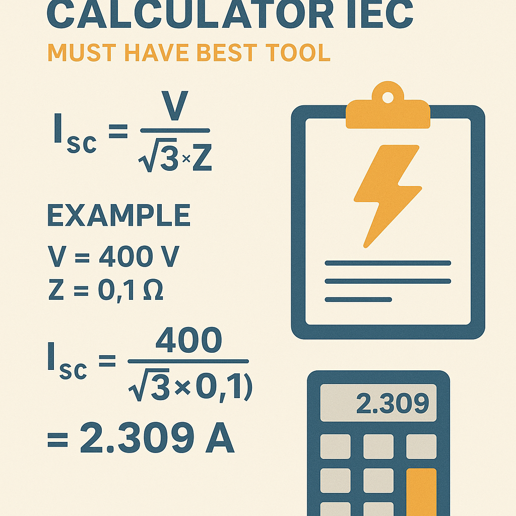
For a three-phase symmetrical short-circuit at a node:
- I_k: steady-state rms short-circuit current (A)
- U_ll: nominal line-to-line system voltage (V)
- √3: square root of 3 (≈1.732)
- Z_th: Thevenin equivalent impedance seen from fault point (ohm)
- U_ll = 11,000 V (11 kV distribution)
- Z_th = 0.5 Ω → I_k = 11000 / (1.732 * 0.5) ≈ 12,700 A
Initial symmetrical short-circuit current for synchronous generators
- I_k'': initial symmetrical short-circuit current (A)
- c: voltage factor according to IEC 60909 (accounts for pre-fault voltage tolerance; typical c between 1.0 and 1.1 for MV/LV networks; e.g., c = 1.05)
- U_n: nominal system line-to-line voltage (V)
- Z_th: Thevenin impedance including generator subtransient reactance Xd'' and network impedances (ohm)
Conversion to per-unit and back
- Z_pu: impedance in per-unit
- Z_actual: impedance in ohm
- S_base: base power (VA), e.g., transformer rated VA
- U_base: base voltage (V)
- I_pu: per-unit current; convert back: I_actual = I_pu * (S_base / (U_base * √3))
Peak current estimation (DC offset influence)
- For X/R = 5, k ≈ 1.8
- For X/R = 10, k ≈ 2.3
- IEC 60909 gives recommended procedures to compute the DC component and peak factor for precise values.
How a professional-level IEC short-circuit calculator functions
A robust tool performs these tasks:- Accepts system topology: single-line diagram, impedance data for transformers, lines, cables, motors, generators, and infeed points.
- Normalizes values to per-unit on consistent bases, applies correction factors (voltage factor c, seasonal adjustments).
- Calculates Thevenin-equivalent impedances at each fault node.
- Computes Ik'', Ik, and peak currents with X/R based DC-offset estimation.
- Generates reports: tabulated currents per bus, recommended breaking capacities, protective device settings, and coordination checks.
Extensive tables with common values
| Nominal System Voltage | Example Application | Typical base V (line-to-line) | Typical transformer rating |
|---|---|---|---|
| Low Voltage (LV) | Building distribution, motor control | 400 V | 50 kVA – 3,150 kVA |
| Medium Voltage (MV) | Industrial feeders, utility distribution | 6.6 kV, 11 kV, 33 kV | 1 MVA – 40 MVA |
| High Voltage (HV) | Transmission and large substations | 66 kV, 110 kV, 220 kV | 50 MVA – 1000 MVA |
| Element | Typical Impedance Representation | Typical Value Examples | Unit |
|---|---|---|---|
| Power transformer %Z | Short-circuit impedance | 4% – 12% (MV/LV), 8% – 16% (HV) | % |
| Synchronous generator Xd'' | Subtransient reactance | 10% – 25% on generator base | % |
| Copper cable impedance | R + jX per km | 0.2 Ω/km + j0.08 Ω/km (example 11 kV) | Ω/km |
| Line inductive reactance | X per km | 0.3 Ω/km (overhead 11 kV) | Ω/km |
| X/R ratios | Network X/R used for DC offset estimation | LV: 5–20; MV: 8–30; HV: 10–50 | Ratio |
Practical calculation workflow for engineers
A recommended stepwise procedure used by calculators and engineers:- Collect nameplate data: transformer %Z, generator Xd'', a.c. line impedances, switchgear ratings.
- Define the system topology and fault location(s) (busbars, feeders, equipment).
- Choose calculation method: IEC 60909 equivalent (for design and type tests) or direct network solution for detailed studies.
- Normalize to base values and compute Thevenin impedances.
- Apply voltage factor c and compute Ik'', Ik, and peak currents.
- Compare results with equipment breaking capacities and protective device settings; iterate design if necessary.
Real example 1 — Industrial 11 kV feeder to 400 V LV transformer
Scenario summary:- Utility supplies an 11 kV feeder; feeder length = 2 km overhead line (R ≈ 0.14 Ω/km, X ≈ 0.35 Ω/km)
- Transformer: 11/0.4 kV, 2 MVA, %Z = 8% (on rated power)
- LV bus fault at transformer low-voltage side (phase-to-phase-to-earth three-phase symmetrical)
- No local generation; neglect motor contribution for initial case
- %Z = 8 → 0.08
- U_11kV = 11,000 V
- S_rated = 2,000,000 VA
Z_tr = 0.08 * (11000^2 / 2,000,000) = 0.08 * (121,000,000 / 2,000,000) = 0.08 * 60.5 = 4.84 Ω
- R_line = 0.14 Ω/km * 2 km = 0.28 Ω
- X_line = 0.35 Ω/km * 2 km = 0.70 Ω
- Z_line = R + jX = 0.28 + j0.70 = |Z_line| = √(0.28^2 + 0.70^2) ≈ 0.75 Ω
Z_th_11kV = Z_line + Z_tr = 0.28 + j0.70 + 4.84 (transformer ≈ taken as real %Z approx resistive negligible reactance assumption here)
For conservative estimate, use magnitude:I_k_11kV = U_ll / (√3 * |Z_th|) = 11000 / (1.732 * 5.59) ≈ 11000 / 9.68 ≈ 1,137 A
Step 5 — Reflect current to LV side (0.4 kV) using transformer turns ratio:I_k_LV = I_k_11kV * (U_11kV / U_0.4kV) = 1,137 * (11000 / 400) = 1,137 * 27.5 ≈ 31,267 A
Step 6 — Check with alternate per-unit method (sanity check):- Base on transformer: S_base = 2 MVA, U_base_LV = 400 V → I_base_LV = S_base / (√3 * U_base_LV) ≈ 2,000,000 / (1.732*400) ≈ 2,887 A
- Transformer %Z = 8% → short-circuit current on LV base ≈ I_base / 0.08 ≈ 2,887 / 0.08 ≈ 36,088 A (initial symmetrical theoretical at transformer's internal terminals)
- Subtracting feeder and source impedance reduces to ≈ 31 kA, close to previous result (differences due to approximations).
- Estimated Ik at LV bus ≈ 31 kA (three-phase rms)
- Initial peak ip assuming k = 2.2 (for X/R typical) → ip ≈ 2.2 * Ik'' ≈ 68 kA
- Equipment selection: LV switchgear must be rated with breaking capacity ≥ 31 kA rms and withstand peak ~68 kA; follow IEC 60909 de-rating practices.
- Include transformer vector group and R/X composition for more precise transformer impedance conversion.
- Consider utility substation impedance and parallel feeders if available; include motor contributions.
- Use c factor per IEC 60909 (e.g., 1.05) to compute initial symmetrical currents for design margins.
Real example 2 — LV 400 V bus with multiple infeed and motor contribution
Scenario summary:- LV bus 400 V supplies three motors and an upstream 11 kV/0.4 kV transformer (S = 1.5 MVA, %Z = 6%)
- Utility short-circuit capacity at HV side: 10 kA (11 kV) reflected to transformer
- Motors: Motor A: 250 kW (Inom 452 A), Motor B: 132 kW (Inom 238 A), Motor C: 90 kW (Inom 162 A)
- Motors contribute up to 4–6 times locked-rotor current during initial fault (subtransient)
- Utility Ik_11kV = 10,000 A at 11 kV
- Reflect to LV using turns ratio: factor = U_11kV / U_lv = 11000 / 400 = 27.5
- Utility contribution at LV: 10,000 * 27.5 = 275,000 A (this seems large because utility short-circuit current given at HV must be converted to equivalent Thevenin impedance before reflection; calculators model impedances rather than direct multiplication)
- Convert all sources to per-unit on a common base S_base (choose 1.5 MVA or larger).
- Compute Thevenin impedance of utility reflecting transformer and HV network; combine in parallel with transformer internal impedance and motor subtransient contributions.
- Assume transformer internal contribution dominates at LV if upstream impedance is relatively high; for accuracy include mutual parallel contributions.
- Motor A contribution ≈ 6 * 452 A ≈ 2,712 A
- Motor B ≈ 6 * 238 A ≈ 1,428 A
- Motor C ≈ 6 * 162 A ≈ 972 A
- Transformer internal Ik'' ≈ 36,083 A (as calculated)
- Motors add ≈ 5,112 A
- Effective Ik'' ≈ sqrt(36,083^2 + 5,112^2) ≈ 36,454 A (vector sum yields small increase because transformer dominates)
- Switchgear at LV must have breaking capacity >= 38 kA rms and peak withstand to ~80 kA.
- Protective device selection: choose breakers/fuses with adequate Icu or Ics higher than Ik'' plus safety margins; ensure coordination with downstream devices and selectivity.
- Arc-flash hazard calculations will use these values to determine incident energy and PPE requirements (IEEE 1584 guidance recommended).
Typical calculator features that professional engineers must evaluate
- Compliance with IEC 60909 versions and interpretation choices (e.g., voltage factor defaults, motor contribution models).
- Ability to include generator and motor subtransient reactances and dynamic contributions.
- Support for mixed units, automatic per-unit normalization, and graphical single-line entry.
- Detailed reporting: per-node Ik'', Ik, ip, X/R ratios, equipment rating checks, and recommended device classes.
- Exportable traceable reports for design review and authority compliance.
Validation, verification, and sensitivity analysis
Good practice requires:- Cross-checking calculator outputs against manual per-unit hand calculations on critical nodes.
- Sensitivity studies: vary upstream impedance, transformer %Z, and motor contributions to examine worst-case and best-case scenarios.
- Documenting assumptions: vector groups, temperature corrections for cable resistance, and whether motors are running or stopped at fault inception.
Reporting and documentation recommended by standards
Reports should include:- Single-line diagram with annotated fault points.
- Assumptions list: voltage tolerances, c-factors, motor contributions, cable temperatures.
- Tabulated results per bus: Ik'', Ik, ip, X/R, required breaking capacity ratings, and recommended device models.
- References to normative standards used for each calculation step (e.g., IEC 60909 clause numbers).
Relevant normative references and authoritative resources
- IEC 60909: Short-circuit currents in three-phase AC systems — International Electrotechnical Commission. See https://www.iec.ch and the IEC Webstore entry for IEC 60909.
- IEC 61439: Low-voltage switchgear and controlgear assemblies — requirements for testing and verification. See https://www.iec.ch.
- IEEE 1584: Guide for Performing Arc-Flash Hazard Calculations — IEEE Xplore provides authoritative arc-flash methodologies: https://standards.ieee.org/standard/1584-2018.html.
- Manufacturer technical guides and calculators: ABB short-circuit calculator and Siemens Power Calculation resources provide practical examples and impedance tables:
- Technical committees and guidance documents from CIGRE and national grid operators often publish impedance and system data for design reference.
Best-practice checklist for selecting a short-circuit calculator
- Standards compliance: supports IEC 60909 and optional IEEE 1584 arc modules.
- Transparency: shows intermediate per-unit steps, Thevenin impedances, and voltage factor usage.
- Component library: transformer, generator, cable/line models, motor locked-rotor models.
- Reporting capabilities: traceable outputs, exportable tables, and diagrams.
- Validation tools: ability to run sensitivity and what-if scenarios, and compare against hand calculations.
- User interface: clear single-line input and batch processing for large substations.
Common pitfalls and how to avoid them
- Neglecting pre-fault load voltage factors—use IEC c-factors to avoid underestimation.
- Incorrectly reflecting impedances across transformers—use per-unit methods for consistency.
- Forgetting motor contributions or assuming motors always contribute full subtransient current—document motor state assumptions.
- Relying solely on single-vendor calculators without validating with independent methods.
Closing engineering thoughts (not a standard heading)
Selecting and using a Short Circuit Capacity Calculator that implements IEC 60909 correctly is essential for safe system design, protection coordination, and equipment selection. Engineers must understand the underlying per-unit and impedance combination methods to validate results and document assumptions for compliance and operational safety.References (authority links repeated for convenience):- IEC 60909 — Short-circuit currents in three-phase AC systems: https://www.iec.ch
- IEC 61439 — Low-voltage switchgear and controlgear assemblies: https://www.iec.ch
- IEEE 1584 — Guide for Performing Arc-Flash Hazard Calculations: https://standards.ieee.org/standard/1584-2018.html
- ABB technical library and calculator resources: https://new.abb.com
- Siemens electrical engineering resources: https://new.siemens.com