This impedance calculator calculates the Z in alternating currents, taking into account the resistance and inductive reactance of the load.
It also shows the impedance formula used in this tool, the impedance definition and the impedance table of transformers according to IEC standard.
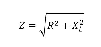
Formula for the calculation of impedance:
The electrical impedance (Z), is the total opposition that a circuit presents to the alternating current. The impedance is measured in ohms and can include resistance (R), inductive reactance (XL) and capacitive reactance (XC). The capacitive reactance generally can not be presented in the eddy current tests, so this term is not included in the equation.
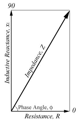 The total impedance is not simply the algebraic sum of resistance and inductive reactance. Since the inductive reactance is 90 degrees out of phase with the resistance and, therefore, its maximum values occur at different times, the vector sum must be used to calculate the impedance. This is illustrated in the image on the right.
If the amount of resistance is represented by the length of the horizontal line and the amount of inductive reactance is represented by the length of the vertical line; then, the amount of impedance is represented by the length of the diagonal line.
Since the lines form a right triangle, the Pythagorean theorem can be used to find the length (value) of the impedance line.
The Pythagorean theorem is written: c 2 = a 2 + b 2
For this application, the variable, a is equal to the resistance, b is equal to the inductive reactance, and c is equal to the impedance. Then, the equation becomes:
Z 2 = R 2 + X L 2
When this equation is rewritten to solve for Z, the impedance equation occurs in the presented form.
Where:
- X L = Inductive reactance (Ω)
- R = Resistance in Ohmnios
- Z = Impedance
Definition of impedance Z:
Are you trying to understand the electrical impedance? Chances are that if you’ve gotten into this topic in the past, you would have some jargon like phasors, phase relationships and even imaginary resistance. What is all this?
We are not all electrical engineers born in the university. Some of us are just playing with electronics in our free time and never find the rigorous mathematics you find in college. But that does not mean that understanding the impedance must be difficult. If you plan to work with electronic devices powered by AC, then you will want to know what the impedance is and what it is doing in a circuit.
The best way to understand electrical impedance is to compare it with something you are already familiar with: resistance . And this is where we are going to offer a summary of the impedance in a sentence in a few words:
The electrical impedance is just one form of resistance that depends on the frequency.
That’s. You can get away now and add one more word to your electrical engineering vocabulary or continue reading. When speaking of impedance, a form of resistance to a current is provided, according to the operating frequency of the circuit. But there is more.
Resistors have a fairly easy job in a DC-powered circuit; They resist the flow of current that flows through some type of metal such as copper. If you introduce a resistance of 220 K ohms in a DC circuit, you will obtain a definite reduction of the current between one side of the resistance and the other. Resistors, like other non-reactive components, may worry less about things like the frequency of the power supply. They’re just going to keep doing what they’re doing, resisting the same amount of current all the time.
But, what happens if you start working with AC-powered electronics? With AC, it is not just a matter of 5 V feeding a circuit. Instead, it has new variables to consider as the particular frequency of alternating current. Here, AC moves up and down at 60 cycles per second (60Hz).
The central point of all this is that in the electronics powered by AC not only need non-reactive components such as resistors to resist the current. It also needs components that can react to changes in current and frequency, such as capacitors and inductors; otherwise, your circuit will not work as expected. Put all this together, and you can almost think of impedance as the big brother of the resistance. The impedance includes both the resistance and the reactance. Or expressed as a relationship:
Impedance = Resistance + Reactance
But what is the reactance?
The reactance comes in two different flavors, depending on which reactive component you are using, these include:
Inductive ballast:
You will see this in the form of electromagnets that change the magnetic field in a circuit, also called an inductor. The inductors will have a low impedance at low frequencies and a high impedance at high frequencies.
Capacitive reactance:
You will see this in the form of an electric field of charge between two conductive surfaces, also called conductor. The drivers have a high impedance at low frequencies and a low impedance at high frequencies.
Place resistors, inductors and capacitors in an AC circuit, and not only have the opportunity to resist electricity, but also have the ability to store and release energy. While a resistor will maintain a constant resistance regardless of the changing conditions, the inductors and capacitors will change their resistance as a function of the frequency of the signal presented to them. And when capacitors and inductors resist and store / release energy, then you have a measure of impedance.
Standard reactance units:
| Prefix Name | Abbreviation | Weight | Equivalent Farad |
| Picofaradio | pF | 10 -12 | 0.000000000001 F |
| Nano farad | nF | 10 -9 | 0.000000001 F |
| Microfarad | μF | 10 -6 | 0.000001 F |
| Mili faradio | mF | 10 -3 | 0.001 F |
| Kilo faradio | kF | 10 3 | 1000 F |
Table impedances recommended in transformers according to IEC
Part 5 of the standard IEC 60076-5: 2000 “Power transformers”, recommend a minimum impedance for transformers
| Short circuit impedance at rated current | ||||
| kVA | Minimum short circuit impedance% | |||
| Above 630 | 4.0 | |||
| 631 | to | 1 250 | 5.0 | |
| 1 251 | to | 2 500 | 6.0 | |
| 2 501 | to | 6 300 | 7.0 | |
| 6 301 | to | 25,000 | 8.0 | |
| 25 001 | to | 40 000 | 10.0 | |
| 40 001 | to | 63 000 | 11.0 | |
| 63 001 | to | 100 000 | 12.5 | |
| Over | 100 000 | > 12.5 | ||
| Note 1: Values for rated power greater than 100 000 kVA are generally subject to an agreement between the manufacturer and the buyer. Note 2: In the case of single-phase units connected to form a three-phase bank, the value of the nominal power is applied to the rating of the three-phase bank. | ||||
Unlike other standards, such as IEEE or AS, which recommend typical values, IEC recommends minimum values.
Since these are minimum values, it does not mean that, as an electrical designer, you can select very high impedances for your transformers. For example, IEC recommends a minimum impedance of 4% Z for a 300 kVA transformer. It does not mean, however, that you can have a Z 6.5%. Although there can be no one to stop it, but the% Z of the transformer is directly proportional to the cost, size and weight of the transformer.
Why do you have to pay more for a transformer when you can buy it cheaper by reducing% Z? The only time you will select a higher impedance for your transformer will be to reduce the fault current in the transformer.
[kkstarratings]