This guide explains converting three-phase and single-phase kW into rectifier input current accurately for engineers.
Includes power factor and efficiency corrections, equations, tables, and worked examples for practical design use.
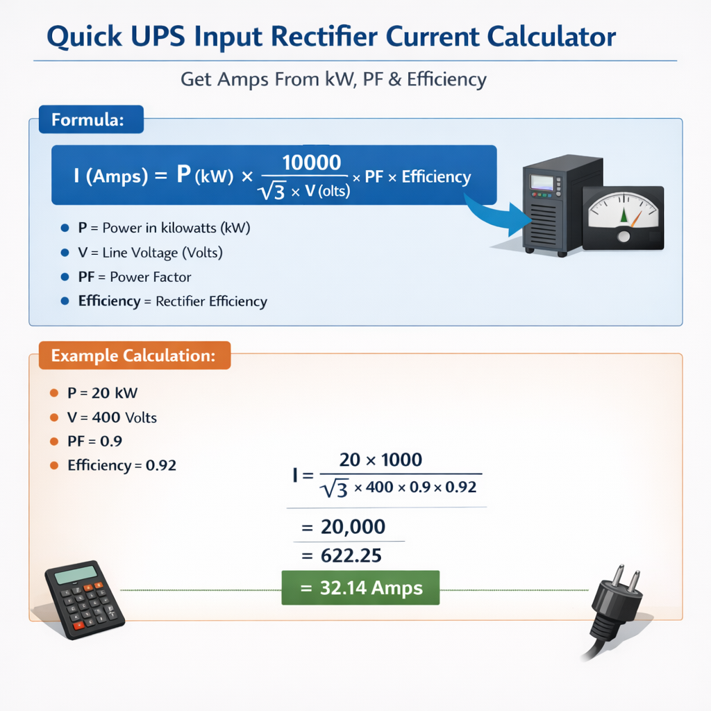
UPS Input Rectifier Current Calculator (Amps from kW, power factor and efficiency)
Scope and applicability
This article provides a rapid methodology to calculate rectifier input current (amps) from kW, power factor, and efficiency. It targets power systems engineers, electrical designers, maintenance technicians, and procurement specialists who must size feeders, protections, and thermal equipment for rectifier-equipped loads.
Fundamental relationships and calculation strategy
The basic approach converts delivered DC or load kW into the required AC input current by accounting for conversion losses (efficiency) and the power factor (PF) of the rectifier front end. Two preliminary conversions are required:
- Compute input real power (P_in) from output kW and efficiency: P_in = kW / Efficiency.
- Compute apparent power (S) from P_in and PF: S = P_in / PF.
Finally, compute line current from apparent power according to the system configuration (single‑phase or three‑phase).
Core formulas (single-line format)
Single-phase line current (amps):
Three-phase line current (amps, line-to-line voltage V_L):
Variable definitions and typical values
- kW — Active output power required by the load, in kilowatts (kW). Typical design values: 0.5 kW to several hundred kW.
- V or V_L — AC system nominal voltage (single-phase V, three-phase line-line V_L). Common values: 120 V, 230 V, 240 V (single-phase); 400 V, 415 V, 480 V (three-phase).
- PF — Power factor (unitless, decimal). For practical rectifiers: 0.55–0.99 depending on topology and correction. Typical default design PFs: uncontrolled diode bridge ≈ 0.6–0.8; thyristor-controlled 0.5–0.95; active front end ≈ 0.95–0.99.
- Efficiency — Rectifier and downstream conversion efficiency (decimal). Typical values: small units 0.85–0.92, medium industrial 0.92–0.97, high-efficiency designs 0.97–0.99.
- I — Calculated line current in amperes (A).
- sqrt(3) — Square root of three ≈ 1.732.
Assumptions, limitations and rectifier behavior notes
- The formulas assume kW is the continuous active power drawn by the DC load (P_out). If the published kW is input power, do not divide by efficiency again.
- PF in the formula must represent the actual measured input power factor (total PF), not only displacement PF. Use measured or vendor-provided PF for the converter under expected load.
- Harmonic distortion affects RMS current, equipment heating, and PF. For rectifiers with high harmonic content, the thermal current can be higher than the calculated value from apparent power alone. Apply correction factors for harmonics when required by standards or when sizing thermal protection.
- For pulsed or cyclic loads, use an energy-equivalent average power for kW or perform time-domain analysis; peak currents can exceed steady-state calculations.
Typical rectifier power factor and efficiency table
| Rectifier Type | Typical PF Range | Typical Efficiency Range | Design Guidance |
|---|---|---|---|
| Single-phase uncontrolled diode bridge (capacitor input) | 0.55 – 0.75 | 0.85 – 0.94 | Expect high harmonic distortion; derate supply and protection accordingly. |
| Three-phase 6-pulse diode bridge | 0.6 – 0.9 | 0.90 – 0.96 | Moderate PF; consider passive filters for harmonics reduction. |
| Thyristor-controlled rectifier | 0.5 – 0.95 (load and firing dependent) | 0.88 – 0.96 | PF variable with firing angle; verify under operating conditions. |
| Active front-end / PWM rectifiers | 0.95 – 0.99 | 0.96 – 0.99 | Near unity PF and low harmonics; preferred for large installations. |
| Switch-mode DC supply (regulated) | 0.7 – 0.99 (with PFC) | 0.88 – 0.98 | Check whether internal PFC is present; varies significantly by design. |
Practical current lookup tables (common voltages and kW)
Below are precomputed current values using the core three-phase formula and single-phase formula, with representative PF and efficiency. These are for quick estimation and comparison; always compute with actual values where possible.
Three-phase currents: PF = 0.90, Efficiency = 0.95
| kW | 400 V (A) | 415 V (A) | 480 V (A) | 690 V (A) |
|---|---|---|---|---|
| 1 | 1.69 | 1.63 | 1.41 | 0.98 |
| 2 | 3.38 | 3.26 | 2.81 | 1.96 |
| 5 | 8.44 | 8.15 | 7.03 | 4.90 |
| 10 | 16.88 | 16.30 | 14.06 | 9.80 |
| 20 | 33.76 | 32.61 | 28.12 | 19.60 |
| 50 | 84.39 | 81.52 | 70.30 | 49.01 |
| 100 | 168.79 | 163.04 | 140.60 | 98.02 |
Single-phase currents: PF = 0.90, Efficiency = 0.95
| kW | 230 V (A) | 240 V (A) | 120 V (A) |
|---|---|---|---|
| 0.5 | 2.54 | 2.44 | 4.63 |
| 1 | 5.08 | 4.87 | 9.26 |
| 2 | 10.17 | 9.74 | 18.52 |
| 5 | 25.42 | 24.36 | 46.32 |
| 10 | 50.84 | 48.73 | 92.64 |
| 20 | 101.69 | 97.46 | 185.28 |
Step-by-step worked examples
Example 1 — Three-phase industrial rectifier, full development
Problem statement: A DC process requires 15.0 kW continuous at the DC bus. The rectifier is a three-phase diode bridge connected to a 400 V line, vendor-specified overall efficiency is 0.96, and measured operating power factor is 0.92. Calculate the required AC line current per phase for steady-state operation.
Step 1 — Compute input power (real):
Step 2 — Compute apparent power S (kVA):
Step 3 — Convert to amps using three-phase formula:
Calculate denominator: 1.732 × 400 = 692.8; × 0.92 = 637.376; × 0.96 = 611.012.
Alternative using S:
S (VA) = 16.978 × 1000 = 16978 VA; I = S / (sqrt(3) × V_L) = 16978 / (1.732 × 400) = 16978 / 692.8 ≈ 24.51 A (rounding differences explained by step order).
Answer: Design for an input line current of approximately 24.6 A. For protection and cable sizing, apply correction for harmonics (if present) and ambient temperature; select next standard breaker/cable size (e.g., 32 A breaker and appropriate cable per local rules), verify inrush and peak currents.
Example 2 — Single-phase rectifier with poor power factor
Problem statement: A lab runs a 7.5 kW DC supply from a single-phase 230 V feed. The device exhibits poor PF = 0.72 (capacitor-input converter), and efficiency is 0.91. Compute expected input current and comment on thermal implications.
Step 1 — Input real power:
Step 2 — Apparent power S:
Step 3 — Single-phase current:
Denominator: 230 × 0.72 = 165.6; × 0.91 = 150.696.
Answer: The expected steady-state RMS current is about 50 A. Because PF is poor and harmonics may be significant, the RMS heating effect could exceed what pure fundamental calculation suggests. Verify conductor derating, breaker trip characteristics, and consider installing PFC or an active front end to reduce thermal stress and potential utility penalties.
Measurement, inrush, harmonics and safety considerations
- Measure actual PF and total harmonic distortion (THD) on-site using a true-RMS meter or power quality analyzer for accurate calculations.
- Rectifier input currents often include high crest factors and short-duration peaks (inrush or capacitor charging). Select protection devices that accommodate inrush or fit with time-delay characteristics.
- Harmonics increase RMS current and heating: when harmonics are present, calculate thermal equivalent current using measured harmonic spectrum or apply multipliers recommended by standards/utility.
- Consider active or passive filtering if THD exceeds acceptable levels per IEEE 519 or local utility interconnection requirements.
- Always apply local code and standard rules (e.g., conductor ampacity, breaker selection, earth fault protection).
Derating and practical corrections for calculator outputs
- Ambient temperature derating: Increase current capacity per cable manufacturer tables if ambient exceeds 30 °C.
- Parallel converters and imbalance: For multiple paralleled rectifiers, evaluate phase balancing and possible circulating currents.
- Transient duty cycles: For cyclical or peak loads, perform time-averaged power integration to derive equivalent continuous kW before using steady-state formulas.
- Harmonic heating correction: For known harmonic spectra, compute I_RMS_total = sqrt(I1^2 + Σ(Ih^2)), and size conductors based on I_RMS_total rather than fundamental-only current.
Cable and protection sizing recommendations (brief)
- Use calculated current (I) to select conductor ampacity according to code tables (e.g., national or regional rules). Apply correction factors for grouping and temperature as required.
- For breakers: choose a device with suitable instantaneous/magnetic trip characteristic to avoid nuisance trips on capacitor inrush, or specify an inrush-limiting device or soft-start.
- Consider selecting the next standard breaker rating above calculated continuous current (for example, calculated 24.6 A → standard 32 A device) only after verifying thermal and derating rules from local code.
How to implement a quick calculator (algorithm outline)
For programmers and engineers implementing a quick field calculator:
- Input: kW (numeric), Voltage (V or V_L), Phase type (1 or 3), PF (decimal), Efficiency (decimal).
- Validation: ensure PF > 0, Efficiency between 0 and 1, voltage positive.
- Compute P_in = kW / Efficiency.
- If phase == 3: I = (kW × 1000) / (1.732 × V_L × PF × Efficiency).
- If phase == 1: I = (kW × 1000) / (V × PF × Efficiency).
- Output: I (amps), S (kVA = P_in / PF), and recommended device sizing guidance (e.g., recommended breaker size, cable ampacity check suggestions).
Best practices when using the calculator
- Always use measured PF and efficiency when available; vendor nominal values are acceptable for initial sizing but verify in commissioning.
- Round currents up to the next practical protective device rating only after checking code ampacity and allowed continuous loading percentages.
- Where harmonics are significant, obtain a harmonic spectrum and compute RMS currents harmonically; consult IEEE 519 or local utility guidelines for harmonic limits and mitigation.
- Document assumptions (PF, efficiency, ambient, duty cycle) in design records and margin selections to support future revisions.
Standards, guidance and authoritative references
Relevant standards and guidance documents that address power factor, harmonics, and rectifier behavior include:
- IEEE 519 — Recommended Practice and Requirements for Harmonic Control in Electric Power Systems. Reference: https://site.ieee.org/pes-pss/ieee-519/
- IEC 61000-3-2 — Limits for harmonic current emissions (applicable to equipment). See https://www.iec.ch/standards
- National Electrical Code (NEC) / NFPA 70 — for conductor ampacity, overcurrent protection, and equipment installation requirements: https://www.nfpa.org/nec
- Manufacturer application notes and technical guides (examples): ABB, Schneider Electric, Siemens application notes on rectifiers and power quality (use vendor sites for model-specific data): https://new.abb.com/ ; https://www.se.com/
- Practical engineering reference on rectifier and PFC behavior: Electrical Engineering Portal articles and tutorials: https://electrical-engineering-portal.com/
Advanced topics and when to consult specialists
Complex scenarios that require deeper analysis or specialist support:
- Large installations (tens to hundreds of kW) with multiple rectifiers feeding shared grids — harmonic interaction and flicker considerations.
- Strict utility interconnection agreements with harmonic limits or penalties; compliance may require filtered or active front-end rectifiers.
- Systems operating at high ambient temperatures, or in containers/closed enclosures where derating and ventilation are critical.
- Non-linear, pulsed, or regenerative loads where bidirectional power flow and braking energy introduce complexities.
Frequently asked practical questions
Q: If I only know kW and voltage, what PF and efficiency should I assume?
A conservative approach is to assume PF = 0.85 and Efficiency = 0.90 for basic uncontrolled rectifiers, unless you can verify better vendor or measurement data. For modern active front ends, assume PF ≈ 0.98 and Efficiency ≈ 0.96–0.98.
Q: Do I need to use total PF or displacement PF in the formula?
Always use total PF (the ratio of real power to apparent power), which includes the effects of harmonics. Displacement PF excludes distortion and therefore underestimates apparent power when harmonics are present.
Q: How do harmonics alter sizing?
Harmonics increase RMS current and heating. Sizing should be based on measured total RMS current, or by calculating harmonic contributions and summing in RMS, then applying conductor and device derating per relevant standards.
Checklist for field verification
- Measure DC output kW and verify whether published kW refers to DC output or AC input.
- Measure input voltage, frequency, PF, and THD under typical operating conditions.
- Confirm rectifier efficiency at operating point from vendor curves or measurement.
- Recalculate currents with measured PF and efficiency; update cable and protection selections accordingly.
- Record measurement data and the calculation steps used for future audits and maintenance.
Final remarks and practical summary
Converting kW to input amps for rectifiers centers on two corrections: efficiency (to find input real power) and power factor (to find apparent power). Use the single-phase and three-phase formulas provided, validate PF and efficiency with measurement or vendor data, and account for harmonics and derating in thermal and protection sizing. Where uncertainty exists, assume conservative PF and efficiency or consult the rectifier manufacturer and power quality specialists.
Applying the calculations correctly reduces risk of undersized conductors, nuisance trips, overheating, and potential utility compliance issues; always document assumptions and verify on commissioning.