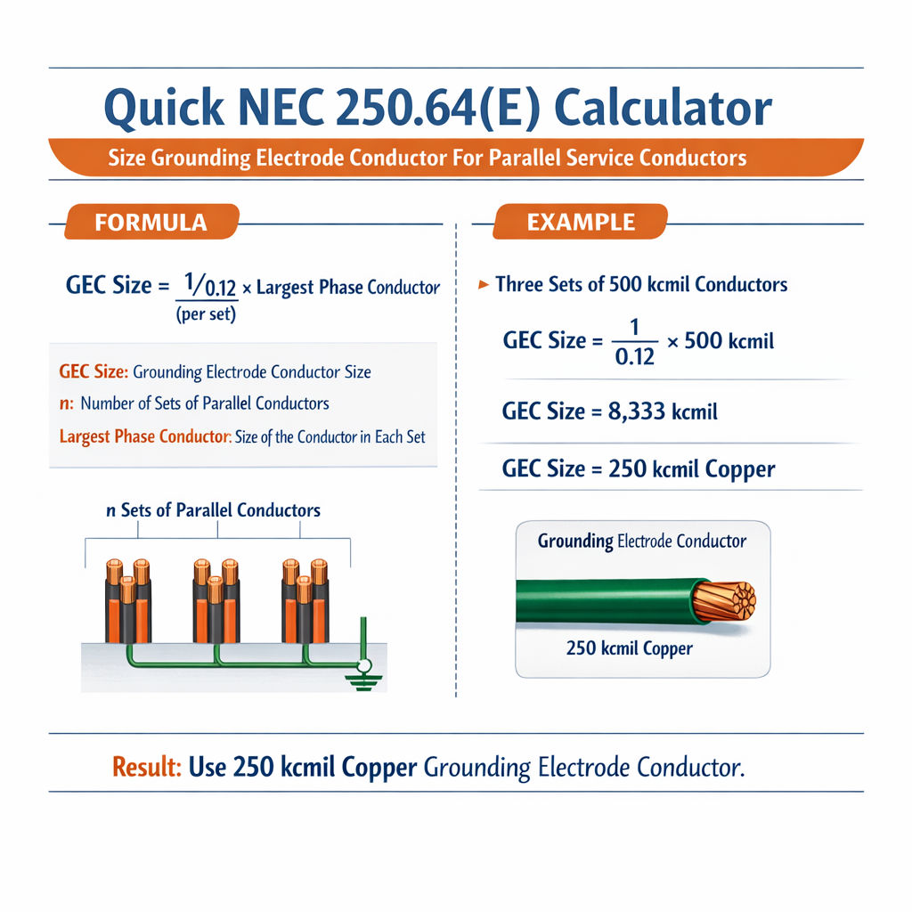
This article explains NEC 250.66 calculator methods for grounding electrode conductor sizing with parallel service conductors.
Includes formulas, AWG tables, worked examples, practical checks, and references to NFPA and IEEE standards.
cURL error 28: Operation timed out after 300002 milliseconds with 0 bytes received
Scope and objective
This document provides a technically precise method to size grounding electrode conductors (GEC) when service conductors are run in parallel. It addresses the conversion of parallel conductors to equivalent circular-mil area, the application of NEC 250.66 guidance, and practical verification checks for installation, bonding, and impedance considerations.
Fundamental concepts and NEC reference
NEC 250.66 and related sections require the grounding electrode conductor to be sized from the largest ungrounded service-entrance conductor or the equivalent circular-mil area where conductors are run in parallel. This article demonstrates the computation steps and how to integrate a Quick NEC 250.66 calculator into field and engineering workflows.
Key normative references
- NFPA 70, National Electrical Code (NEC), Article 250, especially 250.66 and associated notes — https://www.nfpa.org/
- IEEE Std 142 (Green Book) — Grounding of Industrial and Commercial Power Systems — https://ieeexplore.ieee.org/
- IEEE Std 80 — Guide for Safety in AC Substation Grounding — https://ieeexplore.ieee.org/
- U.S. Department of Labor / OSHA guidance on grounding and bonding — https://www.osha.gov/
- UL Standards and manufacturer installation instructions for grounding connectors and clamps — https://www.ul.com/
Terminology and notations
- GEC — Grounding Electrode Conductor
- cmil — Circular Mils (area unit commonly used in NEC and conductor tables)
- n — number of parallel conductors per phase (or ungrounded conductor)
- Aeq — Equivalent circular-mil area for parallel conductors
- A_single — Circular-mil area of a single conductor
- R — Conductor resistance (ohms)
- Ifault — Fault current (amperes) for verification calculations
- Zs — Loop impedance to the ground electrode (ohms)
AWG and circular-mil reference table
| AWG / kcmil | Circular Mils (cmil) | Approx. mm² | Typical use |
|---|---|---|---|
| 14 AWG | 4,110 | 2.08 | Branch circuits |
| 12 AWG | 6,530 | 3.31 | Branch circuits |
| 10 AWG | 10,380 | 5.26 | Small feeders/branch |
| 8 AWG | 16,510 | 8.37 | Feeder/branch |
| 6 AWG | 26,240 | 13.3 | Feeder/branch |
| 4 AWG | 41,740 | 21.2 | Feeder |
| 3 AWG | 52,620 | 26.7 | Feeder |
| 2 AWG | 66,370 | 33.6 | Feeder |
| 1 AWG | 83,690 | 42.4 | Feeder |
| 1/0 AWG | 105,600 | 53.5 | Service/feeder |
| 2/0 AWG | 133,100 | 67.4 | Service/feeder |
| 3/0 AWG | 167,800 | 84.9 | Service/feeder |
| 4/0 AWG | 211,600 | 107.2 | Service/feeder |
| 250 kcmil | 250,000 | 126.7 | Large feeders |
| 350 kcmil | 350,000 | 177.8 | Large feeders |
| 500 kcmil | 500,000 | 253.4 | Large feeders |
Procedure: sizing GEC for parallel service conductors
- Identify the largest ungrounded service conductor size (or sizes if run in parallel).
- Determine the circular-mil area for a single conductor (from AWG table above).
- Compute equivalent circular-mil area: multiply single-conductor cmil by the number of parallel conductors per phase.
- Use NEC 250.66 Table (or code authority table) to map the equivalent circular-mil area to the minimum required GEC size (copper or aluminum).
- Verify connectors, bonding, and mechanical protection; confirm local amendments and manufacturer listings.
Formula set (HTML only)
Example with two parallel conductors:
To convert cmil back to an AWG (approximate lookup), use a lookup table or interpolation. Typical operation:
If Aeq ≤ 41,740 then largest single AWG equivalent ≤ 4 AWG, etc.
Resistance estimate for copper conductor (approximate):
Where:
- R = resistance in ohms (Ω)
- ρ = resistivity of conductor material (copper ≈ 10.37 ohm·cmil/ft at 20°C for the practical unit set)
- L = length in feet
- A = area in circular mils (cmil)
Note: Many practitioners use tabulated standard resistances (ohms/1000 ft) for AWG sizes rather than computing with resistivity directly.
Practical considerations for parallel conductor grouping
- Parallel conductors must be installed per NEC 310.10(H) — same conductor length, material, transposition as needed to ensure equal impedance.
- When computing the GEC, sum the circular-mil areas of the parallel conductors for the largest ungrounded phase conductor.
- For concentric neutral or cable assemblies, use the manufacturer equivalent circular-mil or NEC guidance for equivalent area.
- Bonding jumpers, meter bases, and service equipment connections must accommodate the selected GEC size. Use listed connectors rated for the conductor sizes involved.
Comprehensive table: parallel conductor examples and equivalent circular-mil areas
| Single conductor size | Single conductor cmil | 2 parallel cmil | 3 parallel cmil | 4 parallel cmil | Typical application |
|---|---|---|---|---|---|
| 3/0 AWG | 167,800 | 335,600 | 503,400 | 671,200 | 200–400 A services |
| 4/0 AWG | 211,600 | 423,200 | 634,800 | 846,400 | 300–600 A services |
| 250 kcmil | 250,000 | 500,000 | 750,000 | 1,000,000 | Large services |
| 350 kcmil | 350,000 | 700,000 | 1,050,000 | 1,400,000 | Large services |
| 500 kcmil | 500,000 | 1,000,000 | 1,500,000 | 2,000,000 | Very large services |
| 1/0 AWG | 105,600 | 211,200 | 316,800 | 422,400 | Common for 150–200A |
Applying NEC Table 250.66 (procedural mapping)
NEC Table 250.66 maps the largest ungrounded conductor (or equivalent circular-mil area for parallel conductors) to a minimum GEC size for copper and for aluminum/copper-clad aluminum. The workflow is:
- Compute Aeq (equivalent cmil) as shown above.
- Locate the range in NEC Table 250.66 that contains Aeq.
- Read the minimum GEC for copper and for aluminum in the table.
- If using bonded or multiple grounding electrodes, ensure the physical GEC and electrode electrode bonding meet all NEC mechanical and electrical requirements.
Link to official NEC descriptions and explanatory material (purchase/view may be required):
- NFPA 70 latest edition — https://www.nfpa.org/NEC
- NEC 250.66 commentary and table references — see NFPA code text and code handbook
Worked example 1 — Residential 200 A service using parallel aluminum conductors
Problem statement: A residential 200 A service uses two parallel 2/0 AWG aluminum conductors per phase in service-entrance conduits. Determine the minimum grounding electrode conductor (GEC) size (material: copper and aluminum options) according to NEC 250.66 workflow.
Step-by-step solution
- Identify single conductor size: 2/0 AWG aluminum. From the AWG table, 2/0 cmil = 133,100 cmil (for copper values; for aluminum, the conductor cmil is the same since cmil is area unit).
- Number of parallels per phase, n = 2. Compute equivalent area:
Next, consult NEC Table 250.66: find the row that contains 266,200 cmil equivalent area. For demonstration, common mapping used in NEC handbook shows approximate mapping:
| Equivalent cmil range (approx.) | Minimum GEC copper | Minimum GEC aluminum |
|---|---|---|
| Up to 41,740 | #8 Cu | #6 Al |
| 41,741 — 105,600 | #6 Cu | #4 Al |
| 105,601 — 211,600 | #4 Cu | #2 Al |
| 211,601 — 335,600 | #2 Cu | 1/0 Al |
| 335,601 — 500,000 | 1/0 Cu | 2/0 Al |
| 500,001 — 700,000 | 2/0 Cu | 3/0 Al |
In our example, Aeq = 266,200 cmil which falls in the 211,601 — 335,600 range.
Therefore the minimum GEC (from the illustrative map above) is:
- Copper GEC: #2 AWG copper
- Aluminum GEC: 1/0 AWG aluminum
Practical notes: Confirm these values by checking the specific NEC Table 250.66 in the edition adopted by the authority having jurisdiction (AHJ). Ensure proper listed connectors for copper-to-aluminum transitions and mechanical protection of GEC when installed exposed.
Worked example 2 — Commercial 400 A service using 3 parallel 3/0 copper conductors
Problem statement: A commercial service rated at 400 A uses three parallel 3/0 AWG copper conductors per phase. Determine the minimum GEC size for copper and for aluminum conductor alternative.
Step-by-step solution
- Single conductor size: 3/0 AWG copper = 167,800 cmil (from AWG table).
- Number of parallel conductors per phase, n = 3. Compute equivalent area:
Consult the mapping table used above. Aeq = 503,400 cmil falls into range 335,601 — 500,000 (slightly above) or the next range (500,001 — 700,000). Because 503,400 > 500,000, it falls into 500,001 — 700,000 range.
From the illustrative mapping:
- Minimum GEC copper: 2/0 AWG copper
- Minimum GEC aluminum: 3/0 AWG aluminum
Verification and remarks:
- Since the computed Aeq exceeds 500,000 cmil, use the 2/0 copper GEC to match the NEC mapping table entry.
- Confirm equipment ratings for lugs and connectors that will accept 2/0 copper GEC. For aluminum GEC, ensure 3/0 rated connectors.
- Check local code amendments and AHJ interpretations, as parallel installations sometimes require special documentation to demonstrate equal impedance.
Impedance and fault-clearing verification
Sizing the GEC is necessary but not sufficient for protective-device coordination; verify that the grounding path will permit sufficient fault current flow to trip overcurrent devices.
Loop impedance check (simplified):
Fault current to ground estimate:
I_fault ≈ V_system / Zs
Where V_system is line-to-neutral or line-to-line as appropriate. Ensure that I_fault is sufficient for overcurrent device operation within the required time.
Installation, conductor routing, and connector requirements
- Use listed clamps and connectors sized for the selected GEC material and service conductor material per UL listings.
- Avoid mixing dissimilar metals without proper anti-oxidant compounds and listed connectors; bonding jumpers and GEC must be continuous and mechanically protected where exposed.
- If multiple electrodes are present, the GEC conductor sizing is still determined by NEC 250.66 but each electrode must be bonded per NEC 250.50 and 250.53.
Common pitfalls and practical checks
- Neglecting to sum circular-mil area for parallel conductors — leads to undersized GEC.
- Failing to verify connectors and lug fill for larger GEC sizes (e.g., 1/0 or 2/0 copper) — mechanical conflicts at service equipment are common.
- Assuming aluminum GECs can be used everywhere; some equipment lugs are listed for copper only.
- Not verifying the edition of NEC used by AHJ — Table 250.66 thresholds are stable across editions but always confirm.
Implementing a Quick NEC 250.66 calculator — algorithm and UI considerations
- Input fields: largest ungrounded conductor AWG/kcmil, number of parallel conductors per phase, conductor material (Cu/Al).
- Step 1: Lookup A_single from AWG table (cmil).
- Step 2: Compute Aeq = n × A_single.
- Step 3: Map Aeq to permissible GEC sizes using a stored version of NEC Table 250.66 ranges.
- Step 4: Present both copper and aluminum minimum GEC sizes and conversion notes.
- Step 5: Include warnings and links to NEC 250.66 and AHJ guidance; request confirmation.
UX recommendations:
- Provide live validation and unit selection (AWG vs kcmil).
- Show intermediate computed Aeq value and equivalent single AWG if desired.
- Export calculation summary for plan submittal and AHJ review.
Additional verification examples (brief)
| Service conductors | Parallels | Aeq (cmil) | Suggested GEC Cu | Suggested GEC Al |
|---|---|---|---|---|
| 4/0 Cu | 2 | 423,200 | 1/0 Cu | 2/0 Al |
| 1/0 Cu | 3 | 316,800 | #2 Cu | 1/0 Al |
| 250 kcmil | 2 | 500,000 | 1/0 Cu | 2/0 Al |
References and further reading
- NFPA 70 (NEC), Article 250 — Grounding and Bonding. Official source: https://www.nfpa.org/NEC
- NEC 250.66 and Table 250.66 — consult the edition adopted by your jurisdiction for precise table entries.
- IEEE Std 142 (Green Book) — for grounding system analysis and best practices: https://standards.ieee.org/
- IEEE Std 80 — Substation grounding and safety analysis: https://standards.ieee.org/
- UL White Papers on grounding connectors and listing details: https://www.ul.com/
- OSHA electrical safety publications — https://www.osha.gov/
Final engineering checklist
- Confirm Aeq calculation: Aeq = n × A_single (cmil).
- Verify mapping to NEC Table 250.66 for chosen NEC edition.
- Confirm GEC conductor material, connectors, and lug compatibility.
- Check impedance and fault current path to ensure protective device operation.
- Document calculations and provide to AHJ for plan review when required.
By following the steps and using the AWG/cmil tables and mapping process described, engineers and electricians can implement a Quick NEC 250.66 calculator routine to size grounding electrode conductors when service conductors are paralleled. Always validate against the code edition enforced by the authority having jurisdiction and use listed connectors and installation practices.