This article provides a technical guide for instant GEC size calculation and grounding results accuracy.
Tools and methods described yield quick, precise service SDS ground electrode conductor sizing outcomes safely.
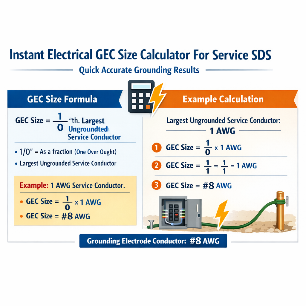
Grounding Electrode Conductor Size Calculator (Based on Largest Service SDS Ungrounded Conductor)
Scope and purpose of an instant GEC sizing calculator
This document defines the engineering basis, algorithms, inputs, and outputs for an instant grounding electrode conductor (GEC) size calculator suitable for service disconnects and service distribution systems (SDS). The focus is on practical, standards-informed techniques to deliver fast and accurate grounding results for designers, installers, and inspectors.
Key normative references and authoritative guidance
- NFPA 70, National Electrical Code (NEC) — relevant articles: 250.4, 250.50–250.68, 250.66 (GEC sizing) — https://www.nfpa.org/
- IEEE Std 81 — IEEE Guide for Measuring Earth Resistivity, Ground Impedance, and Earth Surface Potentials of a Grounding System — https://ieeexplore.ieee.org/
- IEEE Std 142 (Green Book) — Grounding of Industrial and Commercial Power Systems — https://ieeexplore.ieee.org/
- IEEE Std 80 — Guide for Safety in AC Substation Grounding — https://ieeexplore.ieee.org/
- NIST and utility engineering guidance for grounding measurement and verification — https://www.nist.gov/
- IEC 60364 series (where applicable) for international installations — https://www.iec.ch/
Design objectives and performance metrics
The calculator targets three primary outputs:
- Minimum GEC conductor size (cross-sectional area and standard conductor designation) to survive the prospective fault energy and satisfy code/engineering criteria.
- Estimated grounding electrode resistance (single electrode or system of electrodes) using soil resistivity and electrode geometry.
- Estimated fault voltage rise and touch/step potentials for quick safety checks (qualitative or quantitative, depending on inputs).
Required inputs for an instant calculation
- Service data: nominal voltage, phase, largest ungrounded conductor size or ampacity, service overcurrent device rating.
- Prospective fault current at the service neutral or grounded point (Ipf in A). If unknown, supply utility maximum available fault current or use conservative estimates from utility data.
- Fault clearing time (t in seconds) — breaker/ICC fuse clearing or inverse-time calculation for protective devices. If unknown, default conservative values may be used, but must be flagged.
- Conductor material: copper or aluminum (or copper-clad).
- Grounding electrode type, geometry and dimensions: rod length and diameter, plate or ring dimensions, or electrode array geometry.
- Soil resistivity (ρ in ohm·m). If unknown, select typical regional values or perform Wenner test.
- Required or target ground resistance threshold (commonly used values: 25 Ω for acceptance by some utilities, <5 Ω for critical systems).
Default typical values (if user lacks measurement)
- Soil resistivity ρ: 100 Ω·m (moderate); 1000 Ω·m (rocky/dry); 10 Ω·m (moist/clayey).
- Rod diameter d: 16 mm (5/8 inch) typical; length L: 2.44 m (8 ft) common in North America.
- Clearing time t: 0.5 s for typical thermal-magnetic breakers; 0.05–0.1 s for fast breakers; 1.0 s conservative for fuses.
- k factors for adiabatic equation (typical): copper k ≈ 115–143 (depends on conductor type and initial temperature), aluminum k ≈ 95–120. Use conservative lower bound to ensure safety.
Core engineering formulas (HTML only)
1) Conductor DC resistance (approximate):
Where:
- R_conductor is resistance in ohms (Ω).
- ρ_material is electrical resistivity of the conductor material (Ω·m). Typical: copper ≈ 1.724e-8 Ω·m at 20°C, aluminum ≈ 2.82e-8 Ω·m at 20°C.
- length is conductor length in meters (m), one-way or round-trip depending on calculation.
- area is conductor cross-sectional area in square meters (m²). For mm² use area/1e6 conversion.
2) Rod electrode approximate resistance (ER) — classic analytic formula for a single vertical rod in homogeneous soil:
Where:
- R_rod is resistance in ohms (Ω).
- ρ is soil resistivity in ohm·meters (Ω·m).
- L is rod length in meters (m).
- d is rod diameter in meters (m).
- ln is natural logarithm.
3) Parallel electrode combination (simple):
Explain: use this when rods/plates are sufficiently spaced (spacing > 6×rod length is rarely practical; use mutual impedance corrections for closer spacing).
4) Adiabatic thermal sizing (short-circuit energy withstand):
Where:
- S_required is cross-sectional area in mm² (if k uses compatible units).
- I_fault is prospective fault current in amperes (A) that flows through the GEC during the fault.
- t is fault duration in seconds (s) — clearing time.
- k is the material and conductor construction constant (units: A·s^0.5·mm^-2). Typical conservative values: copper k ≈ 115, aluminum k ≈ 95.
5) Voltage rise during fault across GEC/electrode:
Where:
- V_fault is potential rise in volts (V) relative to remote earth.
- I_fault is fault current through grounding path in amperes (A).
- R_GEC is DC resistance of the GEC conductor (Ω).
- R_electrode is measured or modelled electrode resistance (Ω).
- R_connection includes bonding and joint resistances (Ω).
Material constants and common conductor values
| Conductor | Designation | Cross-sectional area (mm²) | Approx. DC resistance at 20°C (mΩ/m) |
|---|---|---|---|
| Copper | 14 AWG | 2.08 | 8.30 |
| Copper | 12 AWG | 3.31 | 5.21 |
| Copper | 10 AWG | 5.26 | 3.28 |
| Copper | 8 AWG | 8.37 | 2.06 |
| Copper | 6 AWG | 13.3 | 1.30 |
| Copper | 4 AWG | 21.2 | 0.82 |
| Copper | 2 AWG | 33.6 | 0.52 |
| Copper | 1/0 | 53.5 | 0.32 |
| Copper | 2/0 | 67.4 | 0.25 |
| Copper | 4/0 | 107.2 | 0.16 |
Notes: resistance values are typical DC resistances per meter (mΩ/m). For conductor sizing use standard tables from manufacturer and adjust for temperature and AC skin effect in high-frequency transient assessments.
| Soil type | Typical resistivity ρ (Ω·m) | Comments |
|---|---|---|
| Peat and highly conductive marsh | 10 – 50 | Very favorable to grounding |
| Clay, loam (moist) | 50 – 150 | Good conductivity |
| Sandy loam | 150 – 500 | Moderate |
| Sandy dry | 500 – 2,000 | Poor to fair |
| Rock, fractured, dry | 2,000 – 20,000+ | Very poor; requires special electrode systems |
Detailed calculation workflow implemented by the instant calculator
- Collect inputs (service rating, Ipf, t, soil ρ, electrode geometry, conductor material).
- Compute single electrode resistance using R_rod formula (if rod) or plate/ring empirical formula when appropriate.
- If multiple electrodes, compute parallel equivalent with corrections for mutual impedance (approximate if spacing small).
- Compute DC resistance of proposed GEC length using R_conductor formula.
- Estimate I_fault that flows in the GEC: for short-circuits at service, the majority of fault current returns via neutral and service bonding; assume I_fault = prospective fault current unless distribution neutral impedance dictates otherwise. Flag uncertainties and request utility data if necessary.
- Apply adiabatic equation to size cross-section that will survive the energy (I_fault and clearing time) without melting beyond acceptable limits. Choose the next standard conductor size larger.
- Compute voltage rise V_fault across grounding path and compare against thresholds for equipment safety; flag excessive step/touch risks for high-voltage or sensitive installations.
- Provide actionable output: recommended conductor (material and AWG/kcmil), expected electrode resistance, expected voltage rise, and recommended mitigation (additional rods, chemical electrodes, conductive backfill, driven arrays, or counterpoise).
Practical calculator heuristics and rounding rules
- Always round up to the next standard conductor size; do not undersize.
- Use conservative k constant for thermal sizing (lower k means larger required area) to account for joints, corrosion, and inhomogeneous heating.
- When soil resistivity is >1,000 Ω·m, do not rely on single rods—recommend driven arrays, buried ring, or conductive backfill and specialist design.
- If prospective fault current is unknown, require user to confirm a conservative assumed value; calculators should not silently assume low fault currents.
- Provide warnings for installations with significant touch/step potential risk (e.g., substation or high-fault current environments) and recommend IEEE Std 80 analysis.
Real example 1 — Residential 200 A service with available fault current
Problem statement: A detached residence has a 200 A main service. Utility reports maximum available prospective fault current at service neutral of 10 kA (10,000 A). The service disconnect clearing time (breaker trip) is 0.2 s. Conductor material is copper. Soil resistivity measured by Wenner test is 250 Ω·m. Ground electrode is a single 8 ft (2.44 m) driven rod, diameter 16 mm (0.016 m). Determine:
- Required minimum GEC conductor cross-section using adiabatic criterion.
- Estimated single rod resistance and expected V_fault during the event.
Step 1 — adiabatic sizing:
Choose conservative k for copper = 115.
Standard conductor mapping: 38.89 mm² lies between 2 AWG (≈33.6 mm²) and 1/0 (≈53.5 mm²). Round up to 1/0 AWG copper (choose 1/0 if typical; conservative designers may pick 2/0).
Step 2 — rod resistance estimate using formula:
Interpretation: A single 8 ft rod in 250 Ω·m soil yields roughly 100 Ω resistance — far above typical acceptance thresholds. Utility target 25 Ω is not met. Additional rods or alternative electrodes required.
Step 3 — expected V_fault across grounding path:
Assume R_GEC (one-way) for 1/0 copper length from service equipment to electrode = length 10 m. Copper DC resistance ≈ 0.32 mΩ/m from table above → R_GEC ≈ 0.00032 Ω/m * 10 m = 0.0032 Ω
R_electrode ≈ 99.6 Ω; R_connection negligible if well-made ≈ 0.01 Ω
V_fault = I_fault * (R_GEC + R_electrode + R_connection) ≈ 10,000 * 99.6132 ≈ 996,132 V ≈ 996 kV relative to remote earth — indicates that the electrode will see essentially the full fault current voltage relative to remote earth, but this number is not realistic as most fault current returns through neutral/utility earth system; this calculation demonstrates the danger of relying on a single high resistance electrode and highlights need for robust electrode system.
Mitigation recommendation: Install multiple rods in a driven array spaced equally around the service with at least 3–4 rods, or a buried ring or plate. For 4 rods in parallel approximate ideal reduction to R_rod/4 = ~25 Ω if well-spaced — still marginal. Consider conductive backfill or chemical electrodes and consult IEEE 81 for accurate multi-rod mutual impedance corrections.
Real example 2 — Small commercial 400 A service, high fault current, and fast clearing
Problem statement: A commercial building has a 400 A service. Utility reports prospective fault current at service of 25 kA (25,000 A). Main breaker clearing time is 0.1 s. Conductor material selected for GEC is copper, and the grounding electrode will be a ring conductor (50 m length) buried around the building at 0.5 m depth. Soil resistivity is measured as 80 Ω·m. Determine:
- Minimum GEC size to survive thermal energy.
- Estimate ring resistance and voltage rise.
Step 1 — adiabatic sizing:
Standard conductor: 68.74 mm² is slightly above 2/0 AWG (~67.4 mm²). Round up to 3/0 or 4/0 depending on local standard sizes; select 3/0 or 4/0 copper — choose 3/0 AWG (~85 mm²) for margin.
Step 2 — ring resistance estimation (simplified):
For a buried ring conductor of length L_ring, an approximate resistance can be estimated using dump-in formula or more accurately using numerical/empirical methods. For quick check use average conductor resistance and return path assumptions. For 50 m ring circumference, copper conductor 4 AWG area 21.2 mm², DC resistance ≈ 0.82 mΩ/m → R_ring_conductor ≈ 0.00082 Ω/m * 50 m = 0.041 Ω.
Soil interaction reduces ground resistance substantially because the ring couples to the surrounding soil. A 50 m ring in 80 Ω·m soil often yields electrode-system resistance of a few ohms (empirical)—for conservative estimator assume R_electrode ≈ 2–5 Ω depending on burial depth and coupling.
Step 3 — expected V_fault:
R_GEC (assume 3/0 copper length 15 m one-way) copper DC resistance ~0.20 mΩ/m for 3/0 → R_GEC ≈ 0.00020 * 15 = 0.003 Ω
Assume R_electrode conservative 3 Ω; R_connection 0.01 Ω.
Interpretation: The electrode system will rise to a high potential relative to remote earth under fault. Even with a low electrode resistance of 3 Ω the fault voltage can be substantial; protection relies on clearing times and safe separation, plus proper equipotential bonding around doors, metalwork, and accessible equipment. Design should aim to reduce electrode resistance further for critical installations or provide equipotential mats and driven stakes around entry points.
Tables for designer decisions: recommended quick-sizing heuristics
| Service rating (A) | Typical max utility fault current (kA) | Conservative min GEC copper (practical) | Notes |
|---|---|---|---|
| 100 A | 5–10 | 8 AWG | Residential small services; confirm with NEC 250.66 |
| 200 A | 5–20 | 1/0 AWG | Common residential/commercial; use adiabatic sizing if high fault current |
| 400 A | 10–30 | 3/0 AWG | Small commercial; ensure electrode resistance low |
| 800 A | 20–50 | 4/0 AWG or larger | Large commercial; coordinate with protection schema |
Note: These heuristics are quick starting points. They do not replace site-specific calculations using prospective fault currents and clearing times. Always verify with local code (NEC Table 250.66 where applicable) and utility requirements.
Mutual impedance and multi-electrode spacing guidance
- Mutual impedance between rods reduces the effective benefit of additional rods when spacing is less than approximately 6× rod length. For practical installations with limited space, use empirical tables or numerical modeling (finite-element or method-of-moments) to assess true benefit.
- For high-resistivity soils, consider vertical arrays with chemical electrodes, conductive backfill (e.g., Bentonite), or continuous buried ring electrodes to achieve target resistance.
- When adding rods: roughly speaking, four well-spaced rods can reduce resistance to ~25% of single rod resistance if spacing and soil are favorable; do not assume linear scaling without analysis.
Verification, measurement and commissioning steps
- Measure soil resistivity on-site using four-point Wenner or Schlumberger method. Document measurements and use average and worst-case values in the calculator.
- Measure final grounding electrode resistance using fall-of-potential tests (three-point) per IEEE 81 procedures.
- Inspect mechanical connections and exothermic welds; measure continuity and verify low resistance bonds using micro-ohm meters if required.
- Record as-built electrode geometry and final measured resistance in the facility documentation; log any mitigations used (chemical electrodes, backfill).
Limitations, caveats and safety warnings
- Instant calculators provide estimates; they do not replace detailed IEEE 80 analysis for substations or facilities with significant touch/step potential concerns.
- Prospective fault current may not all flow in the local electrode; returning paths through utility neutral and remote earth complicate instantaneous voltage calculations. Use conservative assumptions or obtain utility system data.
- Material constants (k factor, resistivities) vary with temperature, alloy, and conductor construction. Use conservative values for safety-critical design.
- Local codes, utility requirements, and AHJ (authority having jurisdiction) rules may mandate larger conductors or specific electrode types; always comply with these requirements.
Calculator output formats and SEO-focused result presentation
- Primary numeric outputs: recommended conductor (AWG/kcmil, mm²), expected electrode resistance (Ω), expected V_fault (V), recommended mitigations.
- Secondary outputs: step-by-step calculation log, formula references, links to applicable NEC/IEEE clauses, printable report for permitting.
- Include contextual recommendations to improve search relevance: "GEC calculator for 200 A service", "ground electrode conductor sizing for service disconnect", "instant grounding results SDS".
References and further reading
- NFPA 70 (NEC). Article 250, Grounding and Bonding. NFPA. https://www.nfpa.org/
- IEEE Std 81-2012, IEEE Guide for Measuring Earth Resistivity, Ground Impedance, and Earth Surface Potentials of a Grounding System. IEEE Xplore. https://ieeexplore.ieee.org/
- IEEE Std 142-2007 (Green Book), Grounding of Industrial and Commercial Power Systems. IEEE Xplore. https://ieeexplore.ieee.org/
- IEEE Std 80-2013, Guide for Safety in AC Substation Grounding. IEEE Xplore. https://ieeexplore.ieee.org/
- NIST Electronic and Magnetic Measurements — grounding measurement techniques. https://www.nist.gov/
Implementation notes for software developers
- Validate all user inputs and provide clear units. Convert units internally to SI for calculation accuracy.
- Provide user-selectable defaults with explicit warnings when inputs are estimates.
- Allow selection of conservative material constants (k). Expose advanced options for experts.
- Include a “what-if” module to add rods, change spacing, and re-evaluate electrode resistance in real time.
- Log calculation provenance: store inputs, formula versions, and normative references for auditability.
Summary of best practices for achieving quick accurate grounding results
- Obtain measured soil resistivity where possible; avoid relying on generic regional values for high-stakes designs.
- Use adiabatic thermal sizing to ensure the GEC survives fault energy; round up to the next standard conductor size.
- Design electrode systems (rings, arrays, plates) rather than relying on a single rod in moderate to high resistivity soils.
- Verify post-installation with fall-of-potential testing and correct any anomalies before energizing critical loads.
- Consult NFPA/NEC, IEEE 81/142/80 and utility requirements for detailed procedures and mandatory sizing rules.
For complex installations or any situation with high prospective fault current or exposure risk, engage a qualified electrical engineer experienced in grounding system design and IEEE/NEC compliance. The instant calculator is a powerful decision-support tool when used with accurate inputs and engineering judgment.