This article explains NEC 250.102(D) load-side bonding jumper sizing and instant code-compliant calculations for contractors.
Includes formulas, tables, worked examples, normative references, and step-by-step sizing procedures for compliance every project.
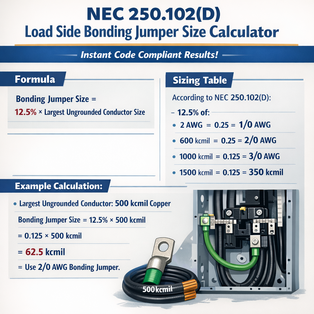
NEC 250.102(D) Load-Side Bonding Jumper Size Calculator (OCPD-based minimum cross-sectional area)
Scope and practical role of a load-side bonding jumper under NEC 250.102(D)
A load-side bonding jumper (LSBJ) is a conductor that establishes an intentional, low-impedance bond between the grounded conductor (neutral) and the grounding electrode system on the load side of the service disconnect or of a separately derived system when the main bonding jumper is not located at the service point. NEC section 250.102(D) governs the use and minimum sizing of load-side bonding jumpers. The practical objective of the LSBJ is to ensure that ground-fault current has a low-impedance return path back to the source so overcurrent devices operate promptly and clear faults. This section explains the accepted sizing methodology, shows specific numerical procedures and formulas in plain HTML, lists common conductor-size selections, and provides two full worked examples. The procedures are compliance-focused and reference NEC Table 250.122 for minimum equipment grounding conductor sizes as required by 250.102(D).Regulatory basis and authoritative references
- NFPA 70, National Electrical Code (NEC). Refer specifically to Section 250.102(D) and Table 250.122 for minimum equipment grounding conductor sizes. See NFPA for the authoritative text: https://www.nfpa.org/
- NEC handbook commentary and explanatory materials for practical application and exceptions.
- IEEE Std 80 and IEEE Std 142 (Green Book) for grounding practices and bonding jumper considerations in large installations: https://standards.ieee.org/
- Manufacturer technical bulletins from major switchgear vendors (e.g., Eaton, Schneider Electric, Siemens) for application examples and product-specific bonding instructions.
Design logic, basic required steps, and decision algorithm
Follow these sequential design steps to size a load-side bonding jumper in a code-compliant way:- Identify the point at which the bond is required (load side of service disconnect or on the secondary of a transformer if bonding there).
- Determine the largest applicable overcurrent protective device (OCPD) rating that protects the circuit(s) or equipment served by the bonded system upstream of the LSBJ.
- Consult NEC Table 250.122 to find the minimum equipment grounding conductor (EGC) size for that OCPD rating and conductor material (copper or aluminum).
- Specify an LSBJ of copper or aluminum with a cross-section no smaller than the EGC size from 250.122; manufacturers commonly require copper for LSBJs in many service applications.
- When the LSBJ must carry continuous load current or be installed in a parallel path, verify ampacity and mechanical protection; apply adjustments, temperature correction, and conductor bundling rules as appropriate.
- Document location, attachment details, and any required marking or insulation per NEC 250.8 and other relevant sections.
Key compliance notes
- NEC 250.102(D) sets minimum sizes; local jurisdictions or equipment manufacturers may require larger sizes.
- When a load-side bond ties into a grounding electrode conductor (GEC) or other conductor, ensure mechanical and electrical continuity and that terminations are accessible and corrosion-protected.
- For separately derived systems (transformer secondaries, generators), additional provisions (250.30, 250.40, etc.) may apply; the bonding jumper sizing logic remains anchored to the EGC sizing rules.
Representative selection table for LSBJ (typical values — verify with NEC Table 250.122)
| Nominal OCPD Rating (A) | Minimum EGC (Copper) — Typical | Minimum EGC (Aluminum) — Typical | Typical LSBJ Selection (Copper) |
|---|---|---|---|
| 15 | #14 | #12 Al equivalent | #14 Cu |
| 20 | #12 | #10 Al equivalent | #12 Cu |
| 30 | #10 | #8 Al equivalent | #10 Cu |
| 40 | #8 | #6 Al equivalent | #8 Cu |
| 60 | #6 | #4 Al equivalent | #6 Cu |
| 100 | #8 | #6 Al equivalent | #8 Cu |
| 150 | #6 | #4 Al equivalent | #6 Cu |
| 200 | #4 | #2 Al equivalent | #4 Cu |
| 400 | 250 kcmil | 300 kcmil Al | 250 kcmil Cu |
| 600 | 350 kcmil | 400 kcmil Al | 350 kcmil Cu |
| 800 | 600 kcmil | 700 kcmil Al | 600 kcmil Cu |
| 1000 | 700 kcmil | 750 kcmil Al | 700 kcmil Cu |
Formulas and conductor property calculations (HTML-only representation)
Below are several plain-HTML formulas you will use when converting between AWG, circular mils, area (mm2), and when checking conductor resistance or verifying parallel runs. Each formula is shown using normal characters; variables are explained and a typical value is given.Conversion: AWG to circular mils (approximate lookup; AWG → cmil is normally obtained from tables)
Example typical values: #14 Cu = 4,110 circular mils; #8 Cu = 16,510 circular mils; #4 Cu = 41,740 circular mils.
Conversion: circular mils to mm²
Variables:
- circular_mils — conductor cross-sectional area in circular mils (cmil)
- area_mm2 — conductor cross-sectional area in square millimetres
Resistance estimate at 20 °C (approximate):
R_ohm_per_ft ≈ resistivity_constant / circular_mils
Variables:
- R_ohm_per_ft — resistance in ohms per foot
- resistivity_constant — copper ≈ 10.37 circular mil·ohm/ft
- circular_mils — conductor circular mils
Parallel-conductor effective cross-section (when two identical conductors in parallel are used):
Variables:
- n — number of identical parallel conductors
- circular_mils_single — cmil per conductor
Explanation of variables and typical values
- AWG — American Wire Gauge designation (e.g., #14, #8, #4). Typical LSBJs are often copper and use standard AWG sizes.
- circular_mils — standard area unit used in US conductor sizing tables.
- area_mm2 — metric area used in international practice and for conversions.
- R_ohm_per_ft — conductor DC resistance per unit length at 20 °C; used for short-circuit heating and voltage drop calculations.
Practical application considerations
- Material: Copper is strongly preferred for bonding jumpers due to superior conductivity and mechanical durability. Aluminum or copper-clad aluminum (CCA) can be used if permitted and properly terminated with compatible connectors.
- Terminations: Use listed lugs or bonding clamps appropriate for the conductor material and environment. Torque values should follow manufacturer data.
- Length and routing: Minimize length and avoid sharp bends to keep loop impedance low. Maintain clear, accessible terminations.
- Parallel conductors: If a single LSBJ cannot meet physical size requirements, parallel conductors of equal length and gauge may be used if allowed by the authority having jurisdiction and termination hardware supports it; ensure equal current distribution and mechanical stability.
- Corrosion protection: Exposed LSBJs subject to corrosive atmospheres require appropriate coatings or copper-clad conductors and corrosion-resistant fasteners.
Worked example 1 — Typical 200 A service where main bonding jumper is at transformer
Scenario: A residential/commercial service has a 200 A main breaker on the load side of a pad-mounted transformer. The main bonding jumper is at the transformer primary/secondary connection, and a load-side bonding jumper is required between the grounded conductor and the grounding electrode conductor at the service disconnect on the load side. Step-by-step:- Identify largest OCPD: 200 A (main breaker rating).
- Consult NEC Table 250.122 (or the representative selection table above). For 200 A, a typical minimum EGC size is #4 copper.
- Therefore, minimum LSBJ size = #4 copper (per 250.102(D) stating LSBJ shall be not smaller than the equipment grounding conductor required by 250.122).
- Confirm physical routing and terminations: use listed #4 Cu lugs rated for bolted connection; tighten to manufacturer torque.
- Verify that the LSBJ length and resistance will allow fault current to flow to clear faults. Optional calculation: approximate conductor resistance and voltage drop for short-circuit duration if desired.
#4 Cu circular_mils ≈ 41,740
R_ohm_per_ft ≈ 10.37 / 41,740 ≈ 0.0002488 ohm/ft
If bonding jumper length = 10 ft one-way (20 ft round trip): R_round_trip ≈ 0.0002488 × 20 ≈ 0.004976 ohm
At a fault current of e.g., 10,000 A, I × R = 10,000 A × 0.004976 Ω ≈ 49.8 V drop — acceptable for clearing and thermal stress is limited by short duration.
Outcome: Select #4 Cu LSBJ, install with listed terminations, document torque and routing. Confirm with local AHJ and with NEC Table 250.122.Worked example 2 — 480 V three-phase motor control center with 400 A feeder
Scenario: An MCC contains a 400 A feeder breaker feeding a large motor bank and switchgear. The service or separately derived system bonding is located upstream and a load-side bonding jumper must be sized to ensure ground-fault clearing on the load side of the feeder breaker per NEC 250.102(D). Step-by-step:- Identify largest OCPD: feeder OCPD = 400 A.
- Using the representative table above, a typical minimum EGC for 400 A is 250 kcmil copper (note: verify with NEC Table 250.122).
- Specify LSBJ = 250 kcmil copper (or the EGC size indicated by the code table for the specific NEC edition).
- Check mechanical terminations: 250 kcmil requires heavy-duty lugs and adequate bending radius; ensure bus terminations and lug ratings support this size.
- Consider fault current and thermal withstand: compute short-circuit thermal stress only if the available fault current and clearing time might require larger cross-section or special bonding jumpers per equipment manufacturer.
R_ohm_per_ft ≈ 10.37 / 250,000 ≈ 0.00004148 ohm/ft
At a hypothetical fault current of 25,000 A, voltage drop = 25,000 × 0.0004148 ≈ 10.37 V; thermal stress over the clearing time should be checked against conductor short-time ratings and the equipment interrupting rating.
Outcome: Install 250 kcmil copper LSBJ with properly rated lugs and protective routing. Confirm with equipment manufacturer if the installer-supplied LSBJ contacts busbars. Record and label the LSBJ.Verification checklist before inspection
- Confirm LSBJ gauge equals or exceeds the EGC size from NEC Table 250.122 for the controlling OCPD.
- Verify conductor material and terminations are compatible and listed for the application.
- Ensure LSBJ routing is as short and direct as practical, with mechanical protection where required.
- Confirm torque values and connector types are per manufacturer instructions.
- Document the calculation with reference to the NEC edition and table used, and include a field drawing showing the bonding location.
Special conditions, exceptions, and practical pitfalls
- Do not reduce LSBJ size based on expected fault current magnitude unless explicitly permitted; NEC requirements are prescriptive and must be followed first.
- If the LSBJ will carry continuous neutral current (rare), verify ampacity and temperature correction as for any current-carrying conductor.
- When using aluminum LSBJs, use connectors listed for aluminum and apply anti-oxidant if required by the connector manufacturer.
- In parallel conductor installations, ensure equal lengths and same gauge conductors; unequal lengths can cause uneven current distribution at fault and are typically not permitted for bonding jumpers unless specifically allowed by listing or AHJ.
Installation details and labeling
- Bonding jumpers should be installed using bolted or clamped connections with hardware rated for the conductor material and environment; inspect for galvanic compatibility and torque to spec.
- Marking: Where visible, label bonding jumpers and note the point of connection, conductor size, and purpose (e.g., "Load-side bonding jumper — NEC 250.102(D)"). This aids inspectors and future maintenance.
- Provide mechanical strain relief where the bonding jumper connects to enclosures or buswork; avoid placing joints where moisture, mechanical abrasion, or vibrations could compromise continuity.
Further reading and normative links
- NFPA 70 (NEC) — official code and table references: https://www.nfpa.org/
- NEC Table 250.122 reference and commentary (consult your edition and AHJ): NFPA 70 Handbook or your jurisdiction's adopted code documents.
- IEEE grounding and bonding guides (for large systems and fault current analysis): https://standards.ieee.org/
- Manufacturer technical guidance — examples:
- Eaton bonding and grounding application notes: https://www.eaton.com/
- Schneider Electric grounding guidance: https://www.se.com/
Summary of practical calculator algorithm for implementation
To implement an instant code-compliant sizing calculator in the field or in software, the algorithm is:- Input: controlling OCPD rating (amps), conductor material (copper/aluminum), NEC edition identifier.
- Lookup: select minimum EGC size from NEC Table 250.122 for the given OCPD and material.
- Output: recommended LSBJ size = minimum EGC size found. Provide optional outputs: circular_mils, mm², resistance per unit length, and suggested termination torque/specs.
- Warnings: if user chooses aluminum, display connection and anti-oxidation warnings; if conductor size exceeds practical lug sizes, recommend parallel conductors or alternate termination solutions and consult AHJ.