Quick, accurate transformer regulation estimates accelerate design decisions and protection coordination activities globally for engineers.
This article provides methods to estimate voltage regulation instantly using impedance power factor relationships analytically.
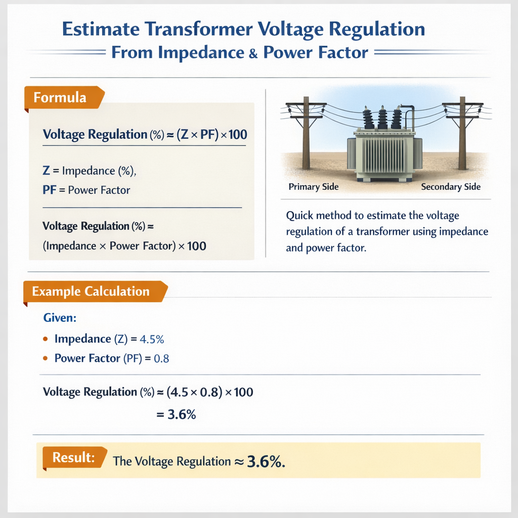
Transformer Voltage Regulation Estimator from Short-Circuit Impedance and Power Factor
Fundamental concepts and practical relevance
Voltage regulation of a transformer quantifies the change in secondary terminal voltage between no-load and full-load conditions at a specified power factor. For rapid engineering assessments and system studies, expressing regulation in per-unit or percent using the transformer's equivalent impedance and the load power factor yields immediate and accurate approximations. This approach avoids repeated phasor diagrams when quick answers are needed for coordination, sizing, stability margins, and short-term voltage support analysis. The instantaneous estimation method presented here uses the magnitude of the transformer's equivalent impedance and its impedance angle (impedance power factor) combined with the load current angle (load power factor) to compute magnitude of the voltage drop. The method is algebraic, fast, robust for engineering-level accuracy, and maps directly to standardized test data (%Z, R/X ratios) typically provided on transformer nameplates or type tests.Theoretical derivation and compact formula
Start from the phasor expression of the voltage drop across the transformer's equivalent series impedance:- I = |I| ∠(-φ), where φ is the load power factor angle (positive for lagging loads).
- Z = |Z| ∠θz, where θz = arctan(X / R) is the impedance angle.
ΔV = |I| ∙ |Z| ∠(θz − φ)
Therefore, the magnitude of the voltage drop is:|ΔV| = |I| ∙ |Z| ∙ cos(θz − φ)
Voltage regulation (percent) = 100 ∙ (|I| / Irated) ∙ |Z|pu ∙ cos(θz − φ)
Using R and X components explicitly, an equivalent and often-used engineering form is:VR% = 100 ∙ Ipu ∙ (Rpu ∙ cos φ + Xpu ∙ sin φ)
Where:- Ipu = |I| / Irated is the load current in per-unit.
- Rpu, Xpu, and |Z|pu are the transformer's series resistance, reactance, and impedance on the chosen per-unit base (commonly transformer rated MVA and nominal terminal voltage).
- φ is positive for lagging power factor (inductive load), negative for leading power factor (capacitive supply).
- θz = arctan(Xpu / Rpu).
Per-unit simplification and immediate engineering use
Using the transformer's rated MVA as the base, %Z is simply |Z|pu = %Z / 100. If R/X ratio is provided, compute Rpu and Xpu as:Let κ = R/X (given), and |Z| = %Z / 100.
Xpu = |Z| / sqrt(1 + κ2)
Rpu = κ ∙ Xpu
Then compute VR% with the formula above. This yields an instant scalar number for regulation at any specified load current and power factor.Detailed explanation of symbols and typical ranges
Provide clear definitions and typical magnitudes so engineers can plug values without ambiguity.- I (A): instantaneous load current magnitude. Typical full-load per-phase current depends on transformer rating and nominal voltage; use Irated = Srated / (√3 ∙ VLL) for three-phase line currents.
- Ipu: load current in per-unit on the transformer MVA base. For full load, Ipu = 1.0.
- R, X (ohm or per-unit): equivalent series resistance and reactance referred to the same winding. Transformers are often characterized by percent impedance (%Z = 100 ∙ |Z|pu).
- φ (degrees): load power factor angle. Typical industrial loads: 0.8 lagging (φ = 36.87°), motors 0.7–0.9 lagging, commercial loads 0.85–0.95 lagging, some corrective capacitive loads leading.
- θz (degrees): impedance angle where tan θz = X / R. Typical θz often ranges from 80°–89° for distribution transformers (low R/X), and 60°–80° for larger power transformers with higher R components.
- VR%: percentage regulation defined as [(Vno-load − Vfull-load) / Vfull-load] ∙ 100 for the selected load direction.
Common transformer data: tables for quick lookup
Use the following practical tables to speed calculations. Values are typical ranges; always prefer manufacturer or test data when available.| Transformer rating (kVA) | Typical %Z (distribution) | Typical %Z (power) | Typical R/X ratio (approx) | Typical θz (°) |
|---|---|---|---|---|
| 50–250 | 3–6% | - | 0.05–0.5 | 78–88 |
| 500–2000 | 4–8% | 4–10% | 0.05–0.3 | 73–87 |
| 5 MVA – 50 MVA | - | 8–16% | 0.05–0.3 | 73–87 |
| Large power (100 MVA+) | - | 10–18% | 0.05–0.2 | 78–84 |
| Load power factor | φ (°) | cos φ | sin φ |
|---|---|---|---|
| Unity | 0.00 | 1.000 | 0.000 |
| 0.95 lagging | 18.19 | 0.950 | 0.312 |
| 0.90 lagging | 25.84 | 0.900 | 0.435 |
| 0.85 lagging | 31.79 | 0.850 | 0.526 |
| 0.80 lagging | 36.87 | 0.800 | 0.600 |
| 0.70 lagging | 45.57 | 0.700 | 0.714 |
Step-by-step worked examples
Below are two full, realistic examples with complete development to illustrate the instant estimation technique for common engineering scenarios.Example 1 — Distribution transformer, 1000 kVA, %Z known, estimate regulation at different PF
Given:- Transformer rating Srated = 1000 kVA (1.0 MVA).
- Rated low-voltage side VLL = 0.415 kV (three-phase secondary typical low-voltage).
- %Z = 6.0% (nameplate).
- R/X ratio = 0.10 (distribution transformer typical, high X).
- Load: full-load (Ipu = 1.0).
- Case A: PF = 1.0 (unity). Case B: PF = 0.80 lagging.
|Z|pu = %Z / 100 = 6 / 100 = 0.06
Step 2 — Compute Xpu and Rpu from R/X ratio κ = 0.10:Xpu = |Z|pu / sqrt(1 + κ2) = 0.06 / sqrt(1 + 0.01)
sqrt(1.01) ≈ 1.0049876, so Xpu ≈ 0.06 / 1.0049876 ≈ 0.05970
Rpu = κ ∙ Xpu = 0.10 ∙ 0.05970 ≈ 0.005970
Step 3 — Compute impedance angle:θz = arctan(X/R) = arctan(0.05970 / 0.005970) = arctan(10) ≈ 84.2894°
Step 4 — Case A: PF = 1.0 (φ = 0°)VR% = 100 ∙ Ipu ∙ (Rpu ∙ cos φ + Xpu ∙ sin φ)
cos 0 = 1, sin 0 = 0 ⇒ VR% = 100 ∙ 1.0 ∙ (0.005970 ∙ 1 + 0.05970 ∙ 0)
Example 2 — Power transformer, 30 MVA, estimate regulation for fractional loading and leading PF
Given:- Srated = 30 MVA.
- Rated voltage (secondary) VLL = 11 kV (for line-to-line basis).
- %Z = 10.0% (typical for some power transformers).
- R/X ratio κ = 0.25 (higher copper losses proportion than small distribution units).
- Load = 0.6 ∙ full load (Ipu = 0.6).
- Case A: PF = 0.9 lagging. Case B: PF = 0.95 leading (capacitor bank dominating).
κ = 0.25 ⇒ Xpu = 0.10 / sqrt(1 + 0.252) = 0.10 / sqrt(1 + 0.0625) = 0.10 / 1.030776 ≈ 0.0970
Rpu = κ ∙ Xpu = 0.25 ∙ 0.0970 ≈ 0.02425
Step 3 — θz = arctan(X/R) = arctan(0.0970 / 0.02425) = arctan(4.0) ≈ 75.9638° Step 4 — Case A: PF = 0.9 lagging (φ ≈ 25.84°). cosφ = 0.9, sinφ = 0.435Practical measurement and test data mapping
Two common ways to obtain the necessary impedance data:- Manufacturer nameplate or type test report: %Z and sometimes R/X or separate R and X at rated conditions.
- Short-circuit (impedance) and open-circuit tests: short-circuit test yields %Z and copper losses (used to determine R at rated temperature). Correction for winding temperature may be necessary.
Rpu = Psc,pu / Ipu2
where Psc,pu is short-circuit loss in per-unit on the transformer base and Ipu = 1.0 for rated short-circuit. Then Xpu = sqrt(|Z|pu2 − Rpu2). Note: Temperature correction of measured R is important: R increases with winding temperature. Apply standard correction using conductor temperature coefficients when using cold- or factory-measured resistance values.Reverse estimation: deduce impedance power factor from measured regulation
You can invert the regulation formula to estimate the impedance phase relationship when you have measured regulation at known load and load power factor. From:VRpu = Ipu ∙ |Z|pu ∙ cos(θz − φ)
So:cos(θz − φ) = VRpu / (Ipu ∙ |Z|pu)
Then:θz = φ + arccos( VRpu / (Ipu ∙ |Z|pu) )
This is useful for system tuning and when trying to back-calculate R/X from field voltage regulation measurements. Ensure the ratio inside arccos is within [−1, 1]; outside this range indicates measurement inconsistency or other network interactions (e.g., additional series impedances, instrument errors).Engineering caveats and accuracy considerations
- Per-unit simplification assumes the impedance is referred to the same voltage and MVA base. Always convert appropriately.
- Temperature dependence: Resistive component changes with temperature; nameplate or test R should be adjusted to operating temperature for highest accuracy.
- Magnetizing branch and load unbalance: The method neglects magnetizing current and off-load shunt components for standard regulation calculations; reasonable for typical loads but account for large no-load currents in some special transformers (e.g., welded core, special designs).
- Parallel elements and system impedance: If external series impedance (feeder reactances, inter-transformer connections) are significant they must be combined into equivalent Z before applying the formula.
- Non-sinusoidal loads: For harmonic-rich currents, use the fundamental component in I and consider additional I2R losses and harmonic impedance implications.
Application in protection, coordination, and power quality studies
Fast estimation of regulation via impedance power factor is useful in:- Voltage drop studies and low-voltage bus design (sizing of conductors, tap-changer settings).
- Protection relay setting coordination where expected voltage under faulted/loaded conditions is required.
- Capacitor bank switching and anti-islanding evaluation (leading PF cases).
- Planning of on-load tap changer (OLTC) range and step settings to maintain voltage profile under varying loads and PFs.
Normative references and authoritative sources
For detailed standards, test methods, and definitions consult these authoritative documents and references:- IEC 60076-1 Power transformers — Part 1: General — general requirements, tests and rating definitions. Official IEC publication: https://www.iec.ch/
- IEEE Std C57.12.00 — General Requirements for Liquid-Immersed Distribution, Power, and Regulating Transformers. See IEEE Xplore or IEEE standards store: https://standards.ieee.org/
- IEEE Std C57.12.90 — Test Code for Liquid-Immersed Distribution, Power, and Regulating Transformers.
- IEEE Recommended Practice for Electric Power Distribution for Industrial Plants (IEEE Std 141, "Red Book") — contains practical guidance on voltage drop and equipment sizing.
- CIGRE and EPRI technical reports on transformer modeling and impedance characteristics for system studies.
Implementation guidance for software and spreadsheets
To implement an instant estimator in a spreadsheet or lightweight script:- Input Srated, Vrated, %Z, and R/X (or R and X).
- Compute |Z|pu = %Z/100 and deduce Rpu, Xpu if needed.
- Enter load Ipu and load PF (signed for leading/lagging convention).
- Compute VR% using VR% = 100 ∙ Ipu ∙ (Rpu ∙ cos φ + Xpu ∙ sin φ).
- Optionally compute terminal voltage under load: Vload ≈ Vrated ∙ (1 − VR%/100) for the scalar magnitude approximation when using the percent regulation definition.
- Verify per-unit conversions and base selection consistency.
- Ensure Rpu ≤ |Z|pu and Xpu ≤ |Z|pu (mathematical consistency).
- Flag negative or impossible arccos arguments in reverse calculations.
Summary of quick formulas for engineers
- Per-unit impedance: |Z|pu = %Z / 100
- Phasor-based regulation magnitude: VR% = 100 ∙ Ipu ∙ |Z|pu ∙ cos(θz − φ)
- Component form: VR% = 100 ∙ Ipu ∙ (Rpu ∙ cos φ + Xpu ∙ sin φ)
- Convert R/X ratio κ to components: Xpu = |Z|pu / sqrt(1 + κ2); Rpu = κ ∙ Xpu
Additional resources and further reading
For deeper modeling (including temperature corrections, frequency variations, and harmonic effects) consult:- IEC 60076 series for transformer testing and rated characteristics (detailed methods for R correction).
- IEEE C57.12.90 test code for accurate measurement procedures and correction factors.
- Textbooks: "Transformer Engineering: Design, Technology, and Diagnostics" and "Power System Analysis" treat detailed phasor methods and network interaction effects.
- IEC 60076 — Power transformers: https://www.iec.ch/
- IEEE Standards — transformer requirements and test codes: https://standards.ieee.org/
- CIGRE technical publications: https://www.cigre.org/