Fast, accurate current conversion tools are essential for engineers designing electrical systems worldwide today precisely.
This article explains converting kW and kVA to amps for single and three phase systems.
Instant current calculator: convert kW or kVA to amps for 1‑phase and 3‑phase systems with power factor
Fundamental equations for kW, kVA and current (amps)
The conversions between active power (kW), apparent power (kVA) and current (A) depend on system configuration and power factor (PF). Use the following core relationships when calculating required current for design, protection and conductor sizing.
Basic formulas (single-phase)
For single-phase circuits:
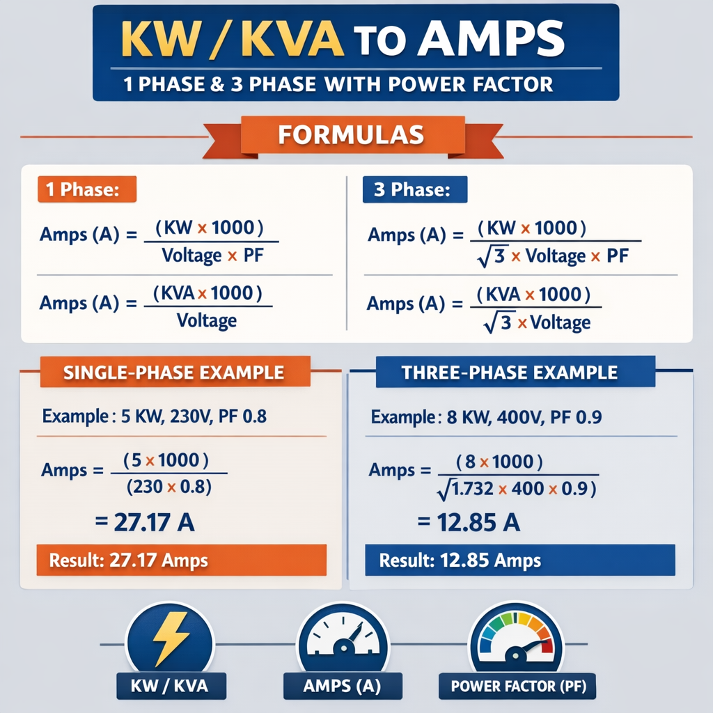
Where:
- I = current in amperes (A)
- kW = active (real) power in kilowatts (kW)
- kVA = apparent power in kilovolt-amperes (kVA)
- V = line voltage (single-phase RMS), in volts (V)
- PF = power factor (unitless, 0–1) for kW→I conversion
Basic formulas (three-phase)
For balanced three-phase circuits (line-to-line voltage):
Where:
- I = line current per phase (A)
- kW = total active power (kW)
- kVA = apparent power (kVA)
- V_LL = line-to-line RMS voltage (V) — common examples: 400 V, 415 V, 480 V
- PF = power factor (unitless)
- √3 = 1.73205 (square root of 3)
Explaining the variables and typical values
Clear understanding of each variable prevents misapplication of formulas, particularly when systems use line-to-neutral voltages, delta or wye connections, or when loads are unbalanced.
Variable definitions and typical examples
- kW (kilowatts) — real power consumed by resistive and active parts of the load. Typical values: 1 kW (heater), 5–20 kW (small industrial equipment), 100–1000 kW (large motors, plants).
- kVA (kilovolt-amperes) — apparent power; transformer and generator ratings are in kVA. Typical: 5 kVA (UPS), 50–500 kVA (commercial transformers).
- PF (power factor) — ratio of real power to apparent power. Typical: 1.0 (pure resistive), 0.8–0.95 (induction motors, industrial loads). Use PF = 0.8 lagging as conservative design baseline for motors.
- V or V_LL — system voltage. Typical single-phase voltages: 120 V, 230 V, 240 V. Typical three-phase voltages: 400 V, 415 V, 480 V, 600 V.
- √3 constant — arises from three-phase phasor relationships; equals approximately 1.73205.
When to use kW vs kVA for current calculation
Choice between kW and kVA depends on what you know and what you need:
- Use kW when the active (real) load is specified and you must account for power factor to find current.
- Use kVA when the available apparent capacity (such as transformer rating) is specified, or when PF unknown; kVA directly gives current without PF.
- For protection and conductor sizing, designers often use kVA for apparent current and then apply PF/efficiency adjustments, diversity and safety factors.
Comprehensive table: Single-phase currents for common kW and kVA values
| kW / kVA | Voltage (V) | PF | Use formula | Calculated Current (A) |
|---|---|---|---|---|
| 1 kW | 120 V | 1.00 | I = (kW*1000)/(V*PF) | 8.33 A |
| 1 kW | 230 V | 0.95 | I = (1*1000)/(230*0.95) | 4.57 A |
| 5 kW | 240 V | 1.00 | I = (5*1000)/(240*1) | 20.83 A |
| 10 kVA | 230 V | — | I = (kVA*1000)/V | 43.48 A |
| 15 kW | 240 V | 0.9 | I = (15*1000)/(240*0.9) | 69.44 A |
| 20 kW | 230 V | 0.8 | I = (20*1000)/(230*0.8) | 108.70 A |
| 50 kVA | 240 V | — | I = (50*1000)/240 | 208.33 A |
Comprehensive table: Three-phase currents for common kW and kVA values
| kW / kVA | V_LL (V) | PF | Use formula | Calculated Line Current (A) |
|---|---|---|---|---|
| 5 kW | 400 V | 0.9 | I = (5*1000)/(√3*400*0.9) | 8.02 A |
| 10 kW | 415 V | 0.85 | I = (10*1000)/(√3*415*0.85) | 16.74 A |
| 25 kW | 480 V | 0.8 | I = (25*1000)/(√3*480*0.8) | 37.65 A |
| 50 kVA | 400 V | — | I = (50*1000)/(√3*400) | 72.17 A |
| 150 kW | 415 V | 0.85 | I = (150*1000)/(√3*415*0.85) | 251.12 A |
| 500 kVA | 480 V | — | I = (500*1000)/(√3*480) | 601.08 A |
Power factor: practical implications and correction
Power factor (PF) impacts current magnitude for a given real power. Low PF increases apparent power and currents, and therefore conductor heating, voltage drop and energy supplier penalties in commercial/industrial tariffs. Understand difference between displacement PF (fundamental) and true PF (includes harmonics).
Practical points about PF
- PF less than 1 increases current: for same kW, I ∝ 1/PF. Example: PF 0.8 yields 25% higher current than PF 1.0.
- PF correction (capacitors, synchronous condensers) reduces reactive current and apparent power, lowering current and energy costs.
- Correct PF sizing must account for harmonic distortion; use detuned filters if harmonics exist (see IEEE 519 guidance).
Design considerations beyond the instant current value
Instant current is the starting point, but safe engineering design requires margins, derating, and regulatory compliance.
Key design parameters
- Continuous load factor: NEC requires continuous loads be sized at 125% for conductor and protection selection where applicable.
- Starting and inrush currents: Motors and non-linear loads can have large transient currents. Protect circuits with appropriate time-delay fuses or motor starters.
- Voltage drop: Long runs require checking voltage drop; target ≤3% for feeders typically.
- Thermal limits and ambient temperature derating: Elevation and ambient temperature increase conductor resistance; apply derating per standards.
- Unbalanced loads in three-phase systems: Check phase currents separately for significant unbalance and neutral sizing.
Worked example 1 — Single-phase heater (step-by-step)
Problem: Determine the current drawn by a 5 kW electric heater connected to a 240 V single-phase supply. Heater is resistive so PF = 1.0. Provide conductor sizing guidance.
Step-by-step solution
Step 1 — Identify known values:
- kW = 5
- V = 240 V
- PF = 1.0
Step 2 — Apply formula for single-phase real power:
Step 3 — Round and apply design multipliers:
- Continuous load? If heater is considered continuous (operates for more than 3 hours), per many regulations use 125% factor: 20.83 * 1.25 = 26.04 A.
- Select conductor and breaker: use standard tables — a 6 mm² copper conductor rated ~32–36 A (referenced per local code) and a nominal breaker rating of 32 A or 40 A depending on coordination and derating. Apply local NEC or IEC rules.
Result: Instant current = 20.83 A. Design current (125%) = 26.04 A → select protection and cables accordingly (e.g., 32 A breaker / 6 mm² copper conductor, verify local code).
Worked example 2 — Three-phase motor load (detailed)
Problem: A three-phase induction motor has a rated output 150 kW, supply voltage 415 V (line-to-line), and nameplate PF = 0.85 (lagging). Determine running line current and required kVA of supply. Consider continuous loading rules.
Step-by-step solution
Step 1 — Known values:
- kW = 150
- V_LL = 415 V
- PF = 0.85
- √3 = 1.73205
Step 2 — Calculate line current from kW:
Compute denominator: 1.73205 * 415 * 0.85 ≈ 611.02 * 0.85? Better calculate accurately:
Step 3 — Apparent power kVA required by supply:
Check via current method: S = √3 * V_LL * I = 1.73205 * 415 * 245.49 ≈ 176470 VA = 176.47 kVA — consistent.
Step 4 — Design considerations:
- Starting current: typical locked-rotor current may be 5–7 times rated; supply and starter selection must address this.
- Continuous loading: if continuous, apply 125% rule to conductor: design current = 245.49 * 1.25 = 306.86 A.
- Select conductor and breaker: use standards and tables; likely choose a cable rated >310 A with appropriate ambient derating; select overcurrent device and motor starter per standards.
- Transformer sizing: provision at least 176.47 kVA, often with margin e.g., 200 kVA transform for practical selection.
Result: Running current ≈ 245.5 A, required apparent power ≈ 176.5 kVA. Use appropriate protection and sizing with derating.
Worked example 3 — kVA to amps for commercial transformer
Problem: A 250 kVA three-phase transformer feeding 480 V distribution. Determine full-load current per phase.
Step-by-step solution
Design notes:
- Transformer rated current ≈ 301 A. Select secondary switchgear and conductors accordingly with thermal and fault considerations.
- Consider inrush and magnetizing current during energization; use appropriate fuses and coordination.
Advanced topics: unbalanced loads, neutral currents and single-phase taps
Three-phase systems with single-phase loads create unbalance. Engineers must calculate phase currents individually and evaluate neutral currents and harmonic-related neutral heating.
Neutral current calculations
For a three-phase wye system carrying unbalanced single-phase loads, neutral current equals vector sum of phase currents. If harmonics exist (particularly triplen harmonics), neutral current can exceed individual phase currents and requires appropriately sized neutral conductor.
- Vector summation must be used: IN = I_A + I_B + I_C (phasor sum)
- For pure arithmetic (worst-case), neutral conductor often sized equal to phase conductor or larger when distortion is high.
Accounting for harmonics and non-linear loads
Non-linear loads (VFDs, UPS, computers) distort currents and reduce displacement PF. Use true power factor or kW/kVA relationships that include harmonic currents. IEEE 519 provides guidance on harmonic limits; consider detuned PF banks or harmonic filters.
Practical guidance for harmonic-rich environments
- Measure total harmonic distortion (THD) and compute true apparent power S_true = V_rms * I_rms considering harmonic components.
- Use harmonic filters (passive tuned or active) to protect capacitors and avoid resonance with system impedance.
- Design neutral conductors for potential increased current from triplen harmonics (3rd, 9th...).
Rounding, safety factors and selection of conductors and protective devices
Most standards require rounding up nominal current to nearest standard breaker rating and selecting conductor with margin for derating. Factor in ambient temperature, grouping derating factors, and conductor insulation temperature ratings.
Common rules of thumb
- Round up current to next standard breaker or fuse size and verify coordination tables.
- Apply continuous load multiplier (often 125%) when load is continuous per local code.
- Apply temperature correction factors for ambient >30°C and derating for conductor bundling.
- Verify voltage drop for long feeders and increase conductor size where necessary.
Extensive reference tables: quick lookup for designers
Below are additional extensive tables for common voltages, kW and PF combinations. Use as quick validation while designing; always verify with precise calculations and local code rules.
| kW | Voltage | PF | Single-phase Current (A) | Three-phase Current (A) |
|---|---|---|---|---|
| 2 | 120 V | 1.0 | 16.67 | — |
| 2 | 230 V | 0.95 | 9.13 | — |
| 3.5 | 240 V | 1.0 | 14.58 | — |
| 7.5 | 230 V | 0.9 | 36.10 | — |
| 15 | 400 V | 0.85 | — | 25.50 |
| 30 | 415 V | 0.9 | — | 46.00 |
| 75 | 480 V | 0.85 | — | 105.75 |
| 200 | 600 V | 0.9 | — | 214.71 |
| 350 | 600 V | 0.85 | — | 335.67 |
| 1000 | 480 V | 0.9 | — | 1348.65 |
Standards and normative references
Designers must follow international and local standards. The most relevant authoritative documents include:
- IEC 60038 — Standard Voltages (lists common nominal voltages): https://www.iec.ch
- IEC 60364 — Electrical installations of buildings (design and safety rules): https://www.iec.ch
- IEEE Std 519 — Recommended Practices and Requirements for Harmonic Control: https://standards.ieee.org
- NFPA 70 (NEC) — National Electrical Code, important for conductors, overcurrent protection and continuous load rules: https://www.nfpa.org
- IEC 60909 — Short-circuit currents in three-phase AC systems (for protection and interruption ratings): https://www.iec.ch
Consult local codes and utility requirements for final equipment selection and approval. Transformer and cable manufacturers provide technical datasheets useful for exact ratings and derating tables.
Best practices for implementing an instant current calculator
Whether implementing a spreadsheet, web tool, or embedded calculator in an engineering app, follow these recommendations to ensure accuracy and regulatory compliance.
Functional requirements
- Allow input in kW or kVA, select single-phase or three-phase, and specify voltage and PF.
- Provide both instant current results and design current with configurable multipliers (e.g., 125% for continuous loads).
- Show intermediate calculations and formulas to aid verification and audit.
- Allow selection of units (V, kW, kVA, A) and typical voltage presets per region (e.g., 230 V, 400 V, 480 V).
- Include warnings for starting/inrush currents and harmonic-prone non-linear loads.
Validation and safety features
- Validate user inputs (zeros, negative values, PF outside 0–1 range).
- Provide links to relevant standards and code extracts for quick reference.
- Offer recommended rounding and selection guidance for breakers and cables, not a substitute for full engineering verification.
Summary of conversion quick-reference formulas
Keep this compact list handy for quick conversions:
- Single-phase, kW → I: I = (kW * 1000) / (V * PF)
- Single-phase, kVA → I: I = (kVA * 1000) / V
- Three-phase, kW → I: I = (kW * 1000) / (√3 * V_LL * PF)
- Three-phase, kVA → I: I = (kVA * 1000) / (√3 * V_LL)
Further reading and authoritative resources
- IEC — International Electrotechnical Commission: https://www.iec.ch
- NFPA (NEC) — National Fire Protection Association: https://www.nfpa.org
- IEEE Standards — IEEE Xplore for IEEE 519 and related documents: https://standards.ieee.org
- Manufacturer application guides — ABB, Siemens, Schneider Electric for transformer and motor protection guidance (visit vendor technical libraries).
Final engineering reminders
Instant current calculators are powerful validation tools but do not replace a full engineering design workflow. Cross-check results with:
- Local electrical codes and utility rules
- Manufacturer datasheets for equipment ratings and inrush characteristics
- Harmonic studies where non-linear loads are significant
- Site-specific ambient temperature and installation conditions affecting conductor ratings
Use the formulas and worked examples above to derive currents quickly, then apply safety margins, continuous-load multipliers, and standards-based derating to select conductors, protective devices, and transformers appropriately.