Designing structures with hanging cables requires precise calculation of the catenary curve length. Accuracy ensures stability, safety, and efficient material use, preventing excessive tension or sag. Catenary calculations apply to bridges, power lines, and architectural arches, considering environmental factors, material properties, and dynamic loads for optimal performance.
Catenary Length Calculator
Compute the true length of a hanging cable (catenary) between two supports. Enter span and sag (or choose alternative inputs).
What is the catenary equation?
How is length calculated?
Which inputs to use?
Formulas used
d = a ( cosh(L/(2a)) − 1 ).Then length:
S = 2·a·sinh(L/(2a)).1. Common Values of Catenary Parameters
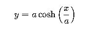
The catenary curve describes the shape of a flexible chain or cable suspended by its ends and acted on by gravity. Its equation is given by:
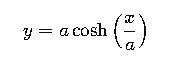
where:
- y is the vertical displacement.
- x is the horizontal displacement.
- a is a constant that defines the shape of the curve.
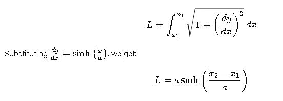
The parameter aaa is determined by the horizontal distance between the supports and the length of the cable. For practical applications, it’s often necessary to calculate the length of the cable between two points. The arc length L of the catenary from x1 to x2 is given by:
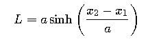
where:
- L is the length of the cable.
- x1 and x2 are the horizontal coordinates of the two points.
- a is the catenary constant.
To assist in practical calculations, the following table provides common values of aaa, horizontal distance (D), and corresponding cable lengths (L) for typical applications:
| Horizontal Distance (D) | Catenary Constant (a) | Cable Length (L) |
|---|---|---|
| 10 m | 5 m | 10.41 m |
| 20 m | 10 m | 20.82 m |
| 30 m | 15 m | 31.23 m |
| 40 m | 20 m | 41.64 m |
| 50 m | 25 m | 52.05 m |
These values are approximate and assume a uniform gravitational field and ideal conditions.
2. Derivation and Explanation of Catenary Formulas
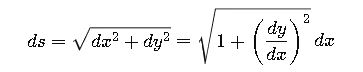
The catenary curve arises from the minimization of potential energy in a hanging chain. To derive the formula for the catenary, consider a small segment of the chain with length ds, which subtends an angle φ\varphiφ with the horizontal.
The vertical and horizontal components of the tension T in the chain are:
- Vertical: Tsinφ
- Horizontal: Tcosφ
The weight of the segment is w ds, where w is the weight per unit length. In equilibrium, the vertical component of the tension balances the weight:
The horizontal component of the tension is constant along the length of the chain, and the total length L of the chain is related to the horizontal distance x by:
Substituting into the equilibrium equation:
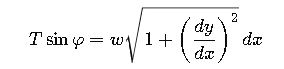
Using the identity cosh2u−sinh2u=1, the solution to this differential equation is:
where a is a constant determined by the boundary conditions.
The length of the cable between two points is obtained by integrating the arc length formula:
This formula is essential for calculating the length of a hanging cable in various engineering applications.
3. Real-World Examples
Example 1: Suspension Bridge Cable
Consider a suspension bridge with cables suspended between two towers 100 meters apart. The cable forms a catenary with a constant a=50 meters. To determine the length of the cable between the towers, we use the formula:
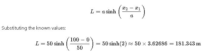
Therefore, the length of the cable is approximately 181.34 meters.
Example 2: Overhead Power Line
An overhead power line is suspended between two utility poles 30 meters apart. The cable has a catenary constant a=15 meters. To calculate the length of the cable, we use the same formula:
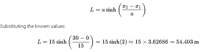
Thus, the length of the power line cable is approximately 54.40 meters.
4. Extended Analysis and Applications
In engineering practice, the catenary curve is utilized in various applications beyond suspension bridges and power lines. For instance, in the design of arches and roofs, understanding the catenary shape allows for efficient load distribution and structural integrity. Moreover, the principles of catenary curves are applied in the design of cable cars, cranes, and even in the study of natural phenomena such as the shape of hanging vines.
Advanced computational methods, including numerical solutions and optimization techniques, are often employed to analyze and design systems involving catenary curves. Software tools and calculators, such as the Catenary Curve Calculator by Omni Calculator, facilitate the calculation of cable lengths, sag, and tension forces in complex scenarios.
Applications in Architecture and Infrastructure
In architectural design, the catenary curve is often employed to create aesthetically pleasing and structurally efficient arches. Famous examples include Antoni Gaudí’s designs in Barcelona, such as the Sagrada Família, where catenary arches distribute weight efficiently, minimizing material usage while maintaining strength.
Bridges also rely heavily on catenary principles. Suspension bridges and cable-stayed bridges use cables shaped by the catenary to carry loads effectively. By understanding the curve, engineers can calculate the appropriate length and tension of cables to ensure safety and stability over large spans.
Overhead power transmission lines provide another real-world application. Utilities must design lines with enough sag to accommodate thermal expansion, wind sway, and ice accumulation. Miscalculating the cable length or tension can lead to line snapping or interference with structures below.
Even in temporary structures, such as tents or exhibition halls, the catenary shape allows designers to span large distances without central supports, providing both stability and open space underneath.
Environmental and Dynamic Factors
Environmental conditions affect catenary structures significantly. Temperature changes cause expansion or contraction of cables, altering sag and tension. Engineers must factor in seasonal variations, ensuring that the cable remains within safe operational limits under both hot and cold conditions.
Wind loads introduce dynamic forces, causing oscillations in the cable. Designers may add dampers or choose cable profiles that reduce wind-induced vibration. Similarly, ice and snow accumulation increase the load on cables, affecting both tension and sag. Accurate calculations based on real-world conditions are essential to prevent structural failures.
Software and Computational Methods
Modern engineering often relies on software tools to simulate catenary behavior under complex conditions. Finite element analysis (FEA) allows for detailed modeling of cable elasticity, distributed loads, and support movement. By running simulations, engineers can predict cable behavior under extreme conditions, optimize material usage, and ensure long-term safety.
Specialized calculators, including online tools and spreadsheet-based models, allow rapid calculation of sag, tension, and required cable length. Many tools incorporate environmental factors, cable weight, and support geometry, helping engineers make precise, reliable decisions in both design and maintenance.
Key Takeaways for Engineers
- Sag and tension are interdependent. Proper design balances the two to ensure stability and longevity.
- Material selection is critical. Tensile strength, elasticity, and environmental resistance determine performance.
- Real-world conditions must be considered. Wind, temperature, ice, and dynamic loads can significantly impact cable behavior.
- Catenary principles are widely applicable. From bridges to power lines, arches, and temporary structures, understanding the curve is essential for safe, efficient design.
- Simulation tools enhance accuracy. Software allows engineers to optimize designs, account for non-linear behavior, and verify safety under multiple scenarios.
By combining theoretical knowledge with practical considerations, engineers can design catenary structures that are both functional and durable, optimizing material use while ensuring safety.