Accurate autotransformer kVA calculation is essential for voltage change applications in electrical systems industrywide today.
This article provides instant accurate methods, formulas, tables, examples, and normative references for engineers globally.
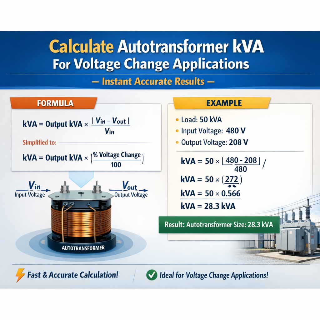
Autotransformer kVA Calculator for Voltage Change (Required Rating and Utilization)
Theory and key formulas for autotransformer kVA in voltage change applications
An autotransformer is a single-winding transformer with a tap that provides a changed voltage level. For voltage change applications the autotransformer requires a smaller VA capacity than an equivalent two-winding transformer because part of the power is transferred conductively through the common winding section while the remaining portion is transferred magnetically through the series section. The critical values to calculate are:- Load apparent power (S_load) — the VA delivered to the secondary/load.
- Series winding apparent power (S_series) — the VA the series portion must handle due to the voltage difference between primary and secondary.
- Autotransformer rated kVA (kVA_auto) — the manufacturer rating that is relevant for procurement and thermal sizing; this is usually the series-winding VA converted to kVA or the combined internal VA depending on supplier conventions.
Basic algebraic formulas (HTML-only)
Load apparent power: S_load = V_secondary × I_load
Series winding apparent power: S_series = (V_primary - V_secondary) × I_load
Alternate form using S_load: S_series = S_load × (V_primary - V_secondary) / V_secondary
Conversion to kVA: kVA_series = S_series / 1000
Saving factor (fractional reduced VA relative to two-winding solution): Saving = 1 - (S_series / S_load) = 1 - (V_primary - V_secondary) / V_secondary
These formulas are algebraically equivalent and valid for step-up and step-down configurations when V_primary and V_secondary are defined consistently. All voltage values are RMS line-to-line for three-phase or RMS line-to-neutral for single-phase calculations, depending on the circuit configuration.Variable explanations and typical engineering values
- V_primary: Supply (primary) voltage in volts (V). Typical industrial values: 480 V, 600 V, 11 000 V, 13 800 V, 33 000 V.
- V_secondary: Desired output (secondary) voltage at the autotransformer tap in volts (V). Typical tap voltages vary ±5%, ±10% from V_primary or specific target distributions like 400 V, 416 V, 440 V, 480 V.
- I_load: Load RMS current in amperes (A). Derived from S_load and V_secondary: I_load = S_load / V_secondary.
- S_load: Apparent power delivered to the load in volt-amperes (VA). Typical values: 10 kVA to multiple MVA depending on application.
- S_series: Apparent power the series winding must carry in VA. This determines the autotransformer VA/kVA procurement and thermal design.
- kVA_series: S_series / 1000, used for ordering and specification.
- Power factor (cosφ): Use actual or assumed PF to size currents; typical PF for motors ~0.85–0.95 leading/lagging; for resistive loads ~1.0.
- V_primary = 480 V, V_secondary = 416 V, S_load = 1000 kVA → I_load = 1000 000 / 416 ≈ 2403.8 A
- V_primary = 11 000 V, V_secondary = 10 500 V, S_load = 5 000 kVA → I_load = 5 000 000 / 10 500 ≈ 476.19 A
Step-by-step calculation workflow for instant accurate results
Follow this workflow to obtain an accurate autotransformer kVA for any voltage change application:- Identify V_primary and the desired V_secondary (line-line for three-phase). Record S_load (VA) required by the load.
- Compute I_load: I_load = S_load / V_secondary. If three-phase and S_load is three-phase VA, ensure V_secondary is the line-to-line voltage and I_load refers to line current.
- Compute S_series: S_series = (V_primary - V_secondary) × I_load.
- Convert to kVA: kVA_series = S_series / 1000. Compare with vendor definitions; some manufacturers quote total autotransformer kVA differently—confirm which value they specify.
- Apply safety factors, harmonics, short-circuit duty, temperature/altitude derating, and inrush or motor-starting multipliers as required by standards and application.
Notes on three-phase systems
For three-phase calculations using line-to-line voltages:- Use line-to-line voltage values for V_primary and V_secondary when S_load is stated as three-phase VA.
- Use S_load (three-phase) directly; line current I_line is I_load = S_load / (√3 × V_secondary) when using three-phase formulas of conventional distribution calculations. However, the autotransformer series-winding VA expression below derived per phase is simpler to apply when using per-phase quantities. Consistency is critical: either compute per-phase S and multiply by 3, or use three-phase forms of the formulas.
Three-phase S_series (three-phase VA): S_series_3ph = 3 × (V_phase_primary - V_phase_secondary) × I_phase
If using line-line voltages and three-phase S_load:Alternate three-phase form: S_series_3ph = S_load × (V_line_primary - V_line_secondary) / V_line_secondary
Extensive tables with common voltage-change scenarios
| Scenario | V_primary (V) | V_secondary (V) | S_load (kVA) | I_load (A) | S_series (kVA) | Series % of Load |
|---|---|---|---|---|---|---|
| A: 480 → 416 (10% approx) | 480 | 416 | 1000 | 2403.8 | 153.85 | 15.4% |
| B: 480 → 440 (8.33%) | 480 | 440 | 500 | 1136.36 | 25.00 | 5.0% |
| C: 600 → 480 (20%) | 600 | 480 | 2000 | 4166.67 | 2500.00 | 125.0% |
| D: 11kV → 10.5kV | 11000 | 10500 | 5000 | 476.19 | 238.10 | 4.76% |
| E: 13.8kV → 12.47kV | 13800 | 12470 | 1500 | 120.34 | 39.87 | 2.66% |
| F: 480 → 416 (100 kVA base) | 480 | 416 | 100 | 240.38 | 15.38 | 15.38% |
Design and procurement considerations
When specifying or procuring an autotransformer for a voltage change application, consider:- Confirm how the vendor rates the autotransformer: some list kVA_series (series winding kVA), others list the full winding equivalent. Ask for both series VA and rated thermal kVA.
- Voltage regulation and tap changer range: specify continuous taps or on-load tap-changer (OLTC) if variation must be corrected under load.
- Short-circuit and inrush currents: autotransformers can have high inrush and fault currents; ensure mechanical and protective devices are rated accordingly.
- Harmonics and non-linear loads: high harmonic content increases heating; apply K-factor or harmonic derating per IEEE/IEC guidance.
- Ambient temperature and altitude: apply derating factors from vendor datasheets and IEC/IEEE environmental clauses.
- Protection: differential protection, overcurrent, ground-fault and overtemperature protection as appropriate for application and codes.
Thermal and overload considerations
Manufacturers typically provide permissible overload curves. Use the kVA_series derived earlier as the base thermal rating and then:- Apply continuous operation margin (typically 10%–25% depending on insulation class).
- Add motor-starting overload allowances if required by the application.
- Increase rating for harmonic-rich loads: use IEEE Std C57.110 or manufacturer guidelines.
Real-world Worked Example 1 — Industrial step-down: 480 V to 416 V supplying a 1200 kVA motor bus
Problem statement:- Supply voltage: V_primary = 480 V (three-phase).
- Desired secondary voltage: V_secondary = 416 V (three-phase bus feeding motors).
- Load apparent power: S_load = 1200 kVA three-phase.
- Assume power factor 0.90 (lagging) for current sizing clarity, but kVA calculations are independent of PF for apparent power.
I_load = S_load / (√3 × V_secondary)
Numeric:I_load = 1 200 000 / (1.732 × 416) = 1 200 000 / 720.512 ≈ 1666.1 A
Step 2 — Compute series winding apparent power (three-phase direct form):S_series = S_load × (V_primary - V_secondary) / V_secondary
Numeric:S_series = 1 200 000 × (480 - 416) / 416 = 1 200 000 × 64 / 416
S_series = 1 200 000 × 0.15384615 = 184 615.38 VA
Step 3 — Convert to kVA for procurement:kVA_series = 184 615.38 / 1000 ≈ 184.62 kVA
Step 4 — Verify per-phase alternative calculation (sanity check):Using I_load and voltage difference: S_series = (V_primary - V_secondary) × I_load × √3
Numeric:S_series = 64 × 1666.1 × 1.732 ≈ 184 600 VA (matches above within rounding)
Step 5 — Apply practical margins and selection:- Select vendor autotransformer rated series kVA at least 10% above calculation for continuous operation: 184.62 × 1.10 ≈ 203.08 kVA → round to standard size 250 kVA autotransformer series rating (depending on vendor availability).
- Confirm thermal curves, short-circuit withstand, and protection coordination for the selected unit.
The series-winding kVA required is ~185 kVA (≈15.4% of the 1200 kVA load). A vendor-rated unit of 250 kVA series capacity would be a practical procurement choice after applying safety margins and confirming vendor definitions.
Real-world Worked Example 2 — Utility step-up: 10.0 kV to 11.0 kV for a 3 MVA substation tie
Problem statement:- We need to step up from V_primary = 10 000 V to V_secondary = 11 000 V (autotransformer used in boosting mode) to support a 3 000 kVA tie to the upstream grid.
- S_load = 3 000 kVA (three-phase).
S_series = S_load × (V_high - V_low) / V_low
Step 2 — Numeric calculation:S_series = 3 000 000 × (11 000 - 10 000) / 10 000 = 3 000 000 × 1000 / 10 000
S_series = 3 000 000 × 0.1 = 300 000 VA
Step 3 — Convert to kVA:kVA_series = 300 000 / 1000 = 300 kVA
Step 4 — Check current:I_load (at V_low side) = S_load / (√3 × V_low) = 3 000 000 / (1.732 × 10 000) ≈ 173.21 A
Step 5 — Series VA via V difference and current:S_series = (V_high - V_low) × I_load × √3 = 1000 × 173.21 × 1.732 ≈ 300 000 VA
Step 6 — Practical selection and margins:- Apply site-specific derating: consider 15% margin for potential overloads and harmonic heating: 300 × 1.15 ≈ 345 kVA → round to 400 kVA standard vendor size.
- Ensure OLTC or fixed taps meet grid regulation requirements and anti-islanding practices for parallel operation.
An autotransformer series-winding rating of ~300 kVA is required to provide a 10% boost for a 3 MVA tie; choose a vendor-rated unit (e.g., 400 kVA series rating) after applying margins and coordination checks.
Practical checks, protections, and normative references
Practical checks before finalizing scheduling or procurement:- Confirm whether vendor quotes kVA for series winding or total internal VA; ensure the specification uses the S_series format in this document.
- Confirm rated continuous current and short-time withstand: confirm mechanical forces and thermal capability per energy input.
- Coordinate protection settings (fuse, relay, transformer differential) and check impact on system coordination studies.
- Perform harmonics analysis for non-linear loads and determine K-factor or derating according to manufacturer guidance.
- IEC 60076 — Power transformers: general guidance on transformer ratings, insulation, testing. Official: https://www.iec.ch
- IEEE C57 series (e.g., IEEE C57.12.00, IEEE C57.12.90) — transformer ratings and test codes. IEEE Standards Association: https://standards.ieee.org
- IEEE Std C57.110 — Guide for evaluating lightning and switching surge performance in transformer application contexts. https://standards.ieee.org/standard/C57_110-2016.html
- Manufacturer technical notes (examples): ABB autotransformers product pages and calculation notes — https://new.abb.com/transformers
- Siemens Power Transformers application guides and autotransformer literature — https://www.siemens-energy.com
- NEMA TR 1 — Additionally for transformer testing and ratings: https://www.nema.org
Extended examples table: quick lookup for engineers
| V_primary (V) | V_secondary (V) | ΔV (V) | Load (kVA) | kVA_series (calculated) | Suggested vendor kVA (rounded) |
|---|---|---|---|---|---|
| 480 | 416 | 64 | 50 | 7.69 | 10 kVA |
| 480 | 416 | 64 | 100 | 15.38 | 20 kVA |
| 480 | 440 | 40 | 250 | 22.73 | 25 kVA |
| 600 | 575 | 25 | 500 | 21.74 | 25 kVA |
| 11 000 | 10 700 | 300 | 2000 | 56.07 | 63 kVA |
| 13 800 | 12 470 | 1330 | 1500 | 160.18 | 200 kVA |
Common pitfalls and troubleshooting
- Mixing line-to-line and line-to-neutral voltages incorrectly: ensure consistency when using three-phase S_load values.
- Confusing S_load with kW: kVA must be used for apparent power; using kW requires dividing by power factor to obtain kVA.
- Assuming autotransformer always reduces overall VA: large percentage changes (e.g., >20%) can require series VA equal to or greater than the load VA (see table entry C), negating savings and making a two-winding transformer preferable.
- Ignoring short-circuit current magnitudes and mechanical forces; autotransformers can transfer high fault currents between interconnected systems.
Checklist for field engineers calculating autotransformer kVA
- Confirm all voltages and whether values are line-line or line-neutral.
- Record S_load (kVA); if only kW available, convert: S_load = kW / cosφ.
- Compute I_load consistently for three-phase or single-phase cases.
- Calculate S_series using S_series = S_load × (V_primary - V_secondary) / V_secondary.
- Convert to kVA and apply thermal, harmonic, altitude deratings and inrush allowances.
- Specify vendor kVA with margins and confirm transformer rating definition with supplier.
- Document protection and mechanical requirements and finalize procurement with referenced standards compliance.
Summary of formulas and quick reference
- S_load = V_secondary × I_load (single-phase) or S_load (three-phase) per system statement.
- I_load = S_load / V_secondary (single-phase) or I_load = S_load / (√3 × V_secondary) for three-phase when S_load is three-phase VA.
- S_series = (V_primary - V_secondary) × I_load = S_load × (V_primary - V_secondary) / V_secondary.
- kVA_series = S_series / 1000.
Final technical recommendations
For instant, accurate engineering results:- Use the algebraic forms provided directly in engineering spreadsheets or calculation tools, ensuring units are consistent.
- Always verify vendor rating conventions and request both series-winding VA and total internal VA numbers.
- When ΔV/V_secondary is small (a few percent), autotransformers provide substantial savings in kVA and cost; when the percentage is large, evaluate two-winding transformers for reliability and protection simplicity.
- Follow IEC/IEEE/NEMA normative guidance for thermal, mechanical and testing requirements and coordinate protection according to utility or site practice.
- IEC 60076 Power Transformers — general standard and parts. https://www.iec.ch/
- IEEE Std C57 family — transformer ratings, tests and guides. https://standards.ieee.org/
- ABB technical notes and product pages for autotransformers. https://new.abb.com/transformers
- Siemens Energy transformer pages and technical application guidance. https://www.siemens-energy.com
- NEMA: Transformer standards and application guidance. https://www.nema.org/