This article explains quick feeder voltage regulation calculation for distribution feeders using R and X.
Focuses practical formulas, examples, tables, and compliance references for accurate regulation from load current analysis.
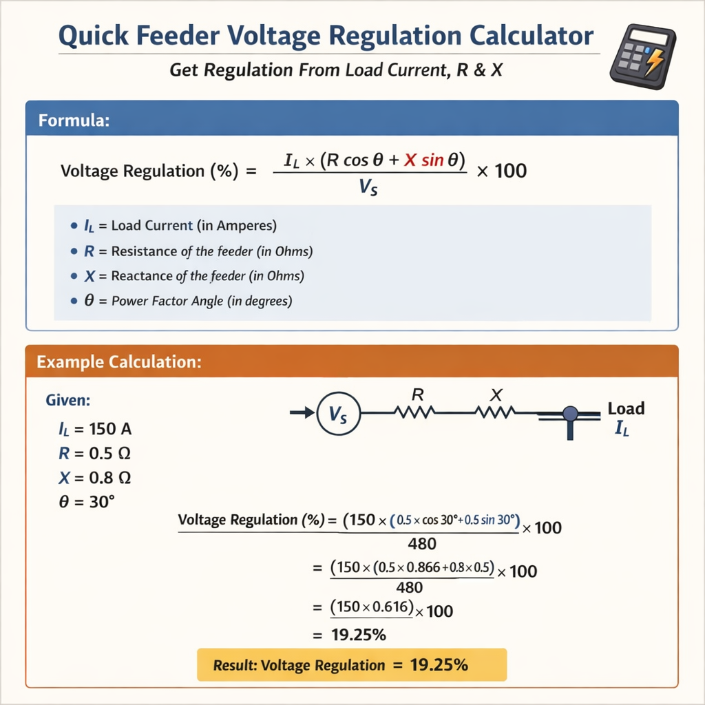
Quick Feeder Voltage Regulation Calculator — Get regulation from Load Current, R and X
Fundamental concepts for quick feeder voltage regulation
Voltage regulation of a feeder is the percentage change in voltage between no-load and full-load conditions measured at the receiving end. For electrical distribution feeders the dominant contributors to voltage change are the series resistance (R) and series reactance (X) of the feeder conductors and the magnitude and phase of the load current.A practical quick-calculator approach reduces the full complex phasor algebra into a simple formula that directly uses load current, conductor R and X, and the nominal system voltage. The objective is to compute the steady-state voltage drop and express it as a percentage of rated voltage (voltage regulation), suitable for preliminary design, operational checks, and compliance screening.Definition of voltage regulation used in calculations
Voltage regulation (%) = ((|V_no_load| - |V_full_load|) / |V_full_load|) * 100For practical distribution feeder estimation, and assuming balanced three-phase conditions, the line voltage drop (magnitude) caused by a balanced load current I is approximated by:Three-phase line voltage drop (V): V_drop = √3 × I × (R_total × cosφ + X_total × sinφ)Where: - I is the line current (A) - R_total = R_per_length × length (Ω) - X_total = X_per_length × length (Ω) - cosφ is the load power factor (lagging positive) - sinφ = √(1 - cos^2φ) for lagging PFVoltage regulation (%) (three-phase) = (V_drop / V_nominal) × 100For single-phase feeders the analogous expression is: V_drop_single_phase = I × (R_total × cosφ + X_total × sinφ) Reg (%) = (V_drop_single_phase / V_nominal_phase) × 100Note: V_nominal for three-phase systems is the line-to-line rated voltage (e.g., 11 kV, 33 kV); for single-phase circuits use the relevant phase voltage.Derivation and assumptions for the quick formula
The quick formula arises from the phasor expression for receiving-end voltage under load: V_R = V_S - I × (R + jX) Ignoring source impedance other than the feeder (appropriate for short feeders or when source internal impedance is negligible), the magnitude difference can be linearized for typical power factors:|V_S| - |V_R| ≈ Re{I × (R + jX) × e^{-jθ}} where θ is the angle of V_R relative to V_S. For balanced loads and small angle differences, the magnitude approximation reduces to the real projection of the complex drop on the system voltage, which gives:V_drop ≈ I × (R × cosφ + X × sinφ) (single-phase) V_drop_3φ ≈ √3 × I × (R × cosφ + X × sinφ) (three-phase)Important assumptions: - Balanced three-phase load (if not balanced, perform per-phase analysis). - Steady-state sinusoidal operation. - Uniform conductor parameters along the run (R and X constant per length). - Power factor is the load’s displacement PF; harmonic distortion effects are ignored.Explanation of every variable and typical value ranges
- I — Load current in amperes (A). Typical distribution feeder currents vary from a few amperes (rural LV) to several hundreds of amperes (large industrial feeders). Example typical values: 50 A, 150 A, 250 A, 600 A.
- R_per_length — Series resistance per unit length (Ω/km or Ω/1000 m). Typical copper cable R at 20 °C: 16 mm² ≈ 1.15 Ω/km; 95 mm² ≈ 0.193 Ω/km; 150 mm² ≈ 0.123 Ω/km. Overhead conductor resistances are larger for the same cross-section due to material and construction.
- X_per_length — Series reactance per unit length (Ω/km). Typical values for underground XLPE cables: 0.05–0.10 Ω/km; for overhead MV lines: 0.25–0.45 Ω/km depending on phase spacing and conductor type.
- length — Conductor length (km). Distribution feeders are commonly from 0.05 km to >10 km.
- R_total = R_per_length × length (Ω).
- X_total = X_per_length × length (Ω).
- V_nominal — Rated system voltage used for percentage calculation. Use line-to-line for three-phase (e.g., 400 V, 11 kV). For single-phase use phase voltage.
- cosφ — Load displacement power factor (lagging positive). Typical values: 0.8 (inductive motors), 0.9 (mixed commercial), 0.95+ (power-factor corrected industrial).
Extensive tables of common conductor R and X values
| Conductor (Cu) cross-section (mm²) | Typical R (Ω/km) at 20 °C | Typical X (Ω/km) (XLPE or comparable) | Typical use |
|---|---|---|---|
| 16 | 1.150 | 0.080 | Small LV branch |
| 25 | 0.727 | 0.080 | LV feeders |
| 35 | 0.524 | 0.075 | LV/short runs |
| 50 | 0.387 | 0.070 | LV mains |
| 70 | 0.268 | 0.065 | LV large feeders |
| 95 | 0.193 | 0.062 | LV/MV cable cores |
| 120 | 0.153 | 0.060 | HV/MV larger cores |
| 150 | 0.123 | 0.058 | High capacity LV feeders |
| 185 | 0.099 | 0.055 | Very large LV feeders |
| 240 | 0.075 | 0.052 | Large industrial feeders |
| Typical overhead MV line (per km) | Approx. R (Ω/km) | Approx. X (Ω/km) | Notes |
|---|---|---|---|
| Small ACSR, tightly spaced | 0.30–0.60 | 0.25–0.45 | 11 kV distribution, spacing dependent |
| Medium ACSR, moderate spacing | 0.12–0.35 | 0.30–0.50 | 33 kV feeders typically lower R/km |
| Long span, single-conductor | 0.50–1.20 | 0.35–0.70 | Higher resistance and reactance |
Quick calculator algorithm and step-by-step procedure
Follow these steps to compute quick feeder voltage regulation from load current, R and X:- Obtain feeder parameters: length (L), R_per_length, X_per_length, system nominal voltage V_nominal, and load current I. Determine load power factor cosφ.
- Compute R_total = R_per_length × L and X_total = X_per_length × L.
- Compute projection term P = R_total × cosφ + X_total × sinφ. This gives the resistive-equivalent of the phasor drop aligned with voltage.
- Compute line voltage drop:
- Single-phase: V_drop = I × P
- Three-phase (line-to-line): V_drop = √3 × I × P
- Compute regulation (%) = (V_drop / V_nominal) × 100.
- Compare result to regulatory or design limits (typical LV design limits: 3–5%, MV allowed up to 5–10% depending on authority and type of circuit).
Two fully developed real examples with detailed solutions
Example 1 — MV three-phase feeder (11 kV) for a rural industrial customer
Problem statement: A balanced three-phase industrial load is connected to an 11 kV feeder that is 5.0 km long. The feeder conductor is an overhead MV conductor with approximate per-kilometre parameters R = 0.400 Ω/km and X = 0.350 Ω/km. The load draws I = 150 A at a lagging power factor of 0.90. Calculate the feeder voltage regulation (%) using the quick method.Step-by-step solution: 1) Given: - V_nominal = 11 000 V (line-to-line) - L = 5.0 km - I = 150 A - R_per_length = 0.400 Ω/km - X_per_length = 0.350 Ω/km - cosφ = 0.90 - sinφ = √(1 - 0.90^2) = √(0.19) = 0.43589 (approx)2) Compute totals: - R_total = R_per_length × L = 0.400 × 5.0 = 2.000 Ω - X_total = X_per_length × L = 0.350 × 5.0 = 1.750 Ω3) Projection term P: - P = R_total × cosφ + X_total × sinφ - P = 2.000 × 0.90 + 1.750 × 0.43589 - P = 1.800 + 0.76282 = 2.56282 Ω4) Three-phase line voltage drop: - V_drop = √3 × I × P - √3 ≈ 1.73205 - V_drop = 1.73205 × 150 × 2.56282 - V_drop ≈ 1.73205 × 384.423 = 665.68 V (rounded)5) Voltage regulation percentage: - Reg (%) = (V_drop / V_nominal) × 100 = (665.68 / 11000) × 100 - Reg (%) ≈ 6.05%Interpretation: - The feeder will experience approximately 6.05% voltage drop at full load current and 0.90 PF lagging. - This exceeds many LV/MV design targets (typical MV allowed vary; confirm with local DNO), so mitigation (larger conductors, tap changer, distributed capacitors, or reduced length) should be considered.Example 2 — LV three-phase feeder (400 V) to a commercial panel
Problem statement: A commercial building has a three-phase LV feeder of length 200 m (0.2 km) feeding a panel with a balanced load drawing 250 A at 0.85 PF lagging. The feeder conductor is a 150 mm² copper XLPE cable with typical parameters R = 0.123 Ω/km and X = 0.058 Ω/km. Calculate the voltage regulation (%).Step-by-step solution: 1) Given: - V_nominal = 400 V (three-phase line-to-line) - L = 0.2 km - I = 250 A - R_per_length = 0.123 Ω/km - X_per_length = 0.058 Ω/km - cosφ = 0.85 - sinφ = √(1 - 0.85^2) = √(0.2775) = 0.52678 (approx)2) Compute totals: - R_total = 0.123 × 0.2 = 0.0246 Ω - X_total = 0.058 × 0.2 = 0.0116 Ω3) Projection term P: - P = R_total × cosφ + X_total × sinφ - P = 0.0246 × 0.85 + 0.0116 × 0.52678 - P = 0.02091 + 0.00611 = 0.02702 Ω4) Three-phase line voltage drop: - V_drop = √3 × I × P - V_drop = 1.73205 × 250 × 0.02702 - V_drop ≈ 1.73205 × 6.755 = 11.70 V (rounded)5) Voltage regulation percentage: - Reg (%) = (V_drop / V_nominal) × 100 = (11.70 / 400) × 100 - Reg (%) = 2.925% ≈ 2.93%Interpretation: - The feeder voltage drop is about 2.93%, generally acceptable against common LV guidance where the total voltage drop from origin to point of utilization is often limited to 4% (with 3% recommended for final sub-circuits in some jurisdictions). This feeder would be compliant in most practical cases, but check local wiring regulations.Practical mitigation measures when regulation is excessive
If the calculated regulation exceeds limits, practical measures include:- Increase conductor cross-section to reduce R and usually X per length.
- Use parallel runs (multiple conductors per phase) to reduce effective R and X.
- Install on-load tap changers at upstream transformers to boost receiving-end voltage under load.
- Limit feeder length or relocate loads (for planning/new installations).
- Power factor correction (capacitor banks) to increase cosφ, reducing the X × sinφ contribution to drop.
- Re-route feeders to reduce mutual coupling or to increase phase spacing for overhead lines to reduce X per km.
Calculator considerations, accuracy, and limitations
A quick feeder voltage regulation calculator using the formula above is excellent for preliminary studies, network planning, and operational checks. However, note these caveats:- Accuracy depends on the precision of R and X values; cable manufacturer data and conductor temperature corrections improve accuracy.
- This method assumes balanced loads. For unbalanced systems, perform per-phase calculations and consider neutral current effects.
- Harmonic currents distort the sinusoidal assumption and produce additional heating and voltage distortion; consult IEEE 519 and harmonic studies for impacted networks.
- Temperature affects conductor resistance; R values given at 20 °C must be corrected for operating temperature using standard correction factors.
- Source internal impedance and transformer impedance can make significant contributions on long or weak-source networks and should be included for high-fidelity studies.
Regulatory and normative references (authoritative sources)
For design limits, recommended practices, and formal requirements consult the following normative sources and technical authorities:- IEC 60364-5-52 — Electrical installations of buildings — Selection and erection of electrical equipment: Voltage drops: https://www.iec.ch/
- IEC 60038 — Standard voltages: https://www.iec.ch/
- IEEE Std 141 (IEEE Green Book) — Electric Power Distribution for Industrial Plants (guidance on voltage drop and feeder design): https://ieeexplore.ieee.org/
- NFPA 70 (NEC) — National Electrical Code (USA) for conductor ampacity and application guidance: https://www.nfpa.org/nec
- CIGRE technical brochures — distribution system studies, overhead line parameters, and MV network planning: https://www.cigre.org/
- Manufacturer cable datasheets and national distribution network operator (DNO) guidance. Example: UK DNO guides or equivalent national operator pages.
SEO-focused checklist for implementing a quick feeder regulation calculator
If building an online calculator or technical page, include these elements for clarity, usability, and SEO:- Clear field labels: I (A), L (km), R (Ω/km), X (Ω/km), V_nom (V), cosφ.
- Default example presets for common scenarios (LV 400 V, MV 11 kV, standard conductor sizes).
- Explanation of units and required input ranges; validation for numeric ranges.
- Provide both numeric output (V_drop, Reg%) and guidance (pass/fail compared to selected limit).
- Allow selection of single-phase or three-phase computation mode.
- Include links to normative references and "how calculated" expandable sections showing the formula steps.
- Provide downloadable detailed worked examples like the two included above to help engineers validate their results.
Summary of practical formulae (quick reference)
- Single-phase V_drop = I × (R_total × cosφ + X_total × sinφ)
- Three-phase (line-to-line) V_drop = √3 × I × (R_total × cosφ + X_total × sinφ)
- R_total = R_per_length × length
- X_total = X_per_length × length
- Reg (%) = (V_drop / V_nominal) × 100
Typical thresholds for decision-making
- LV final circuits: target total voltage drop typically ≤3% at utilization point; total from origin often ≤4–5% depending on national wiring regulations.
- MV feeders: planning limits vary; many utilities accept up to 5–10% but impose tighter limits for sensitive customers.
- If computed regulation > permitted threshold -> select mitigation option(s) from earlier section.
- IEC standards portal — https://www.iec.ch/
- NFPA 70 (National Electrical Code) publications and resources — https://www.nfpa.org/nec
- IEEE Standards and Guides (e.g., IEEE Std 141) — https://standards.ieee.org/
- CIGRE — research and technical brochures on distribution system design — https://www.cigre.org/
- Manufacturer cable datasheets (e.g., major cable vendors) — consult for precise R/X values and thermal ratings.