This guide explains selecting correct electrical service size using calculated load calculators for US sizes.
It covers NEC rules, demand factors, conductor sizing, and practical calculation examples for professionals nationwide.
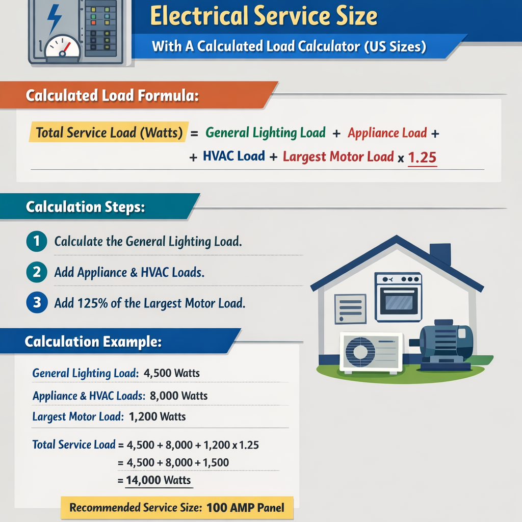
Service Amperage Calculator — Determine service size from calculated load (US sizes)
Scope and purpose of calculated load selection
Selecting the appropriate electrical service size ensures safety, compliance with NEC requirements, minimized installation cost, and reliable operation under design demand. This article explains methods to compute calculated loads for residential, commercial, and small industrial services in US sizes, using established formulas, demand factors, and typical equipment characteristics.Fundamental electrical principles and service types
Single-phase and three-phase services
Service selection differs if the utility supplies single-phase 120/240 V or three-phase 120/208 V, 277/480 V, or other system voltages. The formulas to convert power to current depend on whether the system is single-phase or three-phase.
Basic conversion formulas
Formula (single-phase): I = P / (V × PF)
Variables:
- I = current in amperes (A)
- P = real power in watts (W) or volt-amperes (VA) (use VA for apparent power)
- V = line-to-line voltage in volts (for single-phase 240 V use 240)
- PF = power factor (unitless, typically 0.8–1.0 for motors and mixed loads)
Typical values: PF = 0.95 for resistive heating, PF = 0.85–0.95 for mixed loads, PF = 0.8 for motor-dominant loads.
Formula (three-phase): I = P / (√3 × V × PF)
- I = current in amperes (A)
- P = total real power in watts (W) or VA
- V = line-to-line voltage (e.g., 480 V, 208 V)
- √3 = 1.732
- PF = power factor
Typical PF values as above; when calculating based on nameplate VA, set PF = 1 (use VA directly).
NEC-based methodology for calculated load
NEC Article 220 overview
NEC Article 220 prescribes how to compute the calculated load and apply demand factors for various load categories: general lighting, small appliance circuits, laundry, dwelling unit heating and air conditioning, water heating, ranges, dryers, and fixed appliances.
General procedural steps
- Inventory all fixed and continuous loads with their nameplate ratings (VA or W) and categorize by NEC load groups.
- Apply specific rules (e.g., Section 220.82 for dwelling units, 220.55 for ranges, 220.42 for household electric clothes dryers).
- Apply demand factors and any applicable reductions (e.g., diversity factors for general lighting and small-appliance circuits).
- Sum the calculated loads to obtain total VA, then convert to amperes using system voltage and phase type.
- Select service equipment and conductors with ampacity and short-circuit, coordination, and voltage-drop considerations.
Common loads and typical nameplate values
Below are common household and small commercial load values used in calculated load estimations. These values are illustrative; always use actual nameplate data where available.
| Load Type | Typical Rating (VA or W) | NEC Classification / Notes |
|---|---|---|
| Range (electric, 4 burners + oven) | 8,000 – 12,000 W | NEC 220.55 (apply demand factors based on number of ranges) |
| Electric Dryer | 3,500 – 5,500 W | NEC 220.54 (standard demand or nameplate per dryer) |
| Water Heater (electric) | 3,000 – 4,500 W | Consider if continuous; may require continuous load factor |
| HVAC: Central Heat Pump | 3,000 – 12,000 W (depends on tonnage) | Motors and start currents; apply 125% for continuous motor loads |
| Air Conditioner (central) | 3,000 – 8,000 W | Use nameplate FLA and RLA; consider locked-rotor and starting currents |
| Lighting (residential) | 1,000 – 3,000 W total | Apply NEC general lighting demand factors (per 220.12 and tables) |
| Small appliance circuits | 1,500 VA per circuit | NEC requires at least two 1,500 VA small-appliance circuits per dwelling |
Demand factors and typical application
Demand factors reduce the summed nameplate ratings to reflect realistic simultaneous usage. NEC provides tables and methods; common examples include general lighting, small appliances, and dwelling unit ranges.
| Load Category | Typical NEC Demand Application | Example Demand Factor |
|---|---|---|
| General lighting | Use square footage × VA/ft² as per local adoption (e.g., 3 VA/ft² residential) | Depends on Table 220.12 and local amendments |
| Small-appliance and laundry circuits | At least two 1,500 VA circuits; apply 100% of required circuits | No reduction for required circuits |
| Ranges (multiple) | NEC 220.55: demand allowances based on number of ranges | e.g., first range 8.75 kW, subsequent ranges have reduced factor |
| Electric water heaters | Typically considered individual loads; apply 75% for continuous where applicable | 75% continuous load multiplier when applicable |
Service selection workflow with a calculated load calculator
- Collect nameplate data and categorize loads.
- Enter all items into the calculated load calculator using NEC categories.
- Apply demand factors per NEC Article 220 or local amendments.
- Obtain calculated total VA and convert to amperes using formulas above.
- Adjust for continuous loads: multiply continuous loads by 125% when sizing overcurrent protection.
- Check conductor ampacity, overcurrent device sizing, and voltage drop.
- Select service equipment (meter, main breaker, service conductor size) and specify transformer if utility provides secondary.
Continuous load adjustment
Per NEC, continuous loads (those expected to run for three hours or more) must be multiplied by 125% when selecting overcurrent protective devices.
Formula: I_adjusted = 1.25 × I_calculated_for_continuous_load
- I_adjusted = adjusted current for conductor or breaker sizing
- I_calculated_for_continuous_load = current from load calculation
Conductor ampacity and service equipment selection
After calculating current, select conductors per NEC 310.15(B)(16) ampacity tables, accounting for ambient temperature, conductor insulation type (THHN, XHHW), bundling, and correction factors.
| Common Copper Conductor | Typical Ampacity (75°C column, THHN/XHHW) | Common Use |
|---|---|---|
| AWG 14 | 20 A | Branch circuits for lighting |
| AWG 12 | 25 A | 10–20 A branch circuits |
| AWG 10 | 35 A | Small appliances, subpanels |
| AWG 8 | 50 A | Ranges, dryers (small) |
| AWG 6 | 65 A | Service feeders up to 100 A in some cases |
| AWG 4 | 85–95 A | Service feeders 100 A nominal |
| AWG 2 | 115–130 A | Service feeders 150 A |
| AWG 1/0 | 150–170 A | Service feeders 200 A |
Note: Always confirm ampacity using the exact table and column applicable to the termination temperature rating. NEC 110.14(C) limits conductor ampacity to the lowest rated termination or device rating where applicable.
Voltage drop considerations
Voltage drop should be limited to maintain equipment performance. Recommended maximum total voltage drop for feeders and branch circuits is 5% (3% feeder + 2% branch) for optimal efficiency per industry best practice.
Formula: V_drop = I × R × L × k
- V_drop = voltage drop in volts
- I = current in amperes
- R = conductor resistance per 1000 ft at conductor temperature (ohms/1000 ft)
- L = one-way conductor length in feet
- k = factor for AC systems (for three-phase use √3 or adjust by geometry)
Example 1: Single-family dwelling new service design (detailed)
Scenario: New single-family home, 2,400 ft², equipped with electric range, electric dryer, central a/c (3 ton), electric water heater, lighting and small-appliance circuits per NEC.
Step 1 — Inventory nameplate loads
- General lighting and receptacles: 2,400 ft² × 3 VA/ft² = 7,200 VA
- Small-appliance circuits: 2 required × 1,500 VA = 3,000 VA
- Clothes dryer: 5,000 VA (nameplate)
- Electric range: 12,000 VA (nameplate)
- Water heater: 4,500 VA (nameplate)
- Central AC: 4,000 VA (nameplate) — treat as noncontinuous for diversity, but motor load rules apply
Step 2 — Apply NEC demand factors
Apply NEC 220 procedure for dwelling units:
- General lighting and appliances: Use 7,200 VA + 3,000 VA = 10,200 VA. NEC Table 220.82 reduction and demand table application: For the first 3,000 VA, apply 100% of those VA plus certain percentages beyond; for simplicity in this example, apply standard dwelling method: first 3,000 VA at 100% + remainder at 35% per NEC 220.82 (illustrative).
Compute applied lighting/appliance demand (example simplified):
- First 3,000 VA = 3,000 VA
- Remainder = 10,200 − 3,000 = 7,200 VA
- Remainder demand = 7,200 × 0.35 = 2,520 VA
- Total = 3,000 + 2,520 = 5,520 VA
Step 3 — Add fixed appliance loads
- Dryer: use 5,000 VA (NEC 220.54 allows specific rules; assume nameplate)
- Range: apply NEC 220.55 allowance. For a 12 kW range, the demand allowance might be 8.75 kW for the first range (illustrative), so use 8,750 VA.
- Water heater: 4,500 VA; if not continuous treat at 100% unless continuous rule applies.
- AC: 4,000 VA — motor loads are added at full value; consider starting currents separately for conductor sizing.
Step 4 — Sum calculated loads
- Lighting and small appliances (calculated) = 5,520 VA
- Dryer = 5,000 VA
- Range allowance = 8,750 VA
- Water heater = 4,500 VA
- AC = 4,000 VA
- Total VA = 5,520 + 5,000 + 8,750 + 4,500 + 4,000 = 27,770 VA
Step 5 — Convert to amperes at 240 V single-phase
Formula: I_total = P_total / V
- P_total = 27,770 VA
- V = 240 V
- I_total = 27,770 / 240 = 115.7 A
Step 6 — Apply continuous load multiplier and sizing
If any portion is continuous (e.g., water heater and maybe AC), apply 125% rule for breaker sizing. Conservative approach: apply 125% to the largest continuous loads or to the entire load for main OCPD per local practice.
- Assume total continuous equivalent requires 125%: 115.7 × 1.25 = 144.6 A
- Select standard service size: 150 A service accommodates 144.6 A with margin.
Step 7 — Verify conductor ampacity and voltage drop
- Choose conductors: 3/0 copper or 2/0 copper for 150 A service depending on termination ratings; often 2/0 copper THHN is used for 150 A.
- Check voltage drop for service length: calculate V_drop and ensure less than recommended 3% for feeder portion.
Result — Recommended equipment
- Service equipment: 150 A, 120/240 V single-phase main breaker
- Service conductors: sized per ampacity tables and termination ratings (confirm local code)
Example 2: Small commercial 3-phase service calculation (detailed)
Scenario: Small retail shop with the following equipment: HVAC rooftop unit 7.5 kW (three-phase motor), lighting and receptacles total 6 kW, small kitchen oven 6 kW (single-phase 240 V), miscellaneous loads 3 kW. Utility provides 480 V 3-phase service.
Step 1 — Inventory nameplate loads and split phases
- HVAC rooftop: 7.5 kW (three-phase)
- Lighting/receptacles: 6 kW (can be phased balanced across three phases)
- Kitchen oven: 6 kW (single-phase 240 V) — will be a split-phase or separate transformer; for simplicity add as 6 kW at 240 V equivalent converted to 480 V side via transformer losses or treat as separate service; here account as 6 kW on one phase equivalent load
- Miscellaneous equipment: 3 kW (balanced)
Step 2 — Aggregate three-phase loads
- Total three-phase load (balanced components): HVAC 7.5 kW + lighting 6 kW + misc 3 kW = 16.5 kW. (Assume kitchen oven served separately; if served from same service via transformer, include transformer capacity.)
Step 3 — Convert to amperes on 480 V three-phase
Formula: I = P / (√3 × V × PF)
- P = 16,500 W
- V = 480 V
- Assume PF = 0.9 for mixed commercial load
- I = 16,500 / (1.732 × 480 × 0.9) = 16,500 / (748.2) ≈ 22.06 A
Step 4 — Add single-phase oven load consideration
If the oven is served through a step-down transformer or separate 240 V leg, account for its VA on the service side. If connected to the 480 V system via an autotransformer with minimal phase imbalance, convert its VA to service side:
- Oven = 6,000 VA; convert to equivalent three-phase current: I_oven_eq = 6,000 / (√3 × 480) ≈ 7.22 A
- Total service current approximate = 22.06 + 7.22 = 29.28 A
Step 5 — Apply demand and continuous factors
- Assume no major demand reductions; apply 125% for continuous portions (e.g., lighting if continuous during business hours): 29.28 × 1.25 = 36.6 A
- Select standard three-phase service: 60 A or 100 A depending on future expansion. In practice select 100 A 480 V 3-phase service to allow expansion and harmonics handling.
Step 6 — Select conductors and OCPD
- Use conductor ampacity tables for 480 V 3-phase service. For 100 A, select appropriate copper or aluminum conductors per table and terminal ratings.
- Coordinate with protective devices, transformers, and ensure available short-circuit current ratings.
Result — Recommended equipment
- Service equipment: 480 V 3-phase 100 A main breaker
- Transformer sizing: if oven is on a 240 V winding, provide appropriate transformer (e.g., 15 kVA) sized with inrush considerations
- Conductor selection: per NEC 310.15(B)(16) and termination temperature limits
Transformer and utility considerations
- When a transformer is used to provide low-voltage loads, include transformer VA rating and apply appropriate temperature rise and inrush current considerations.
- Coordination with utility: confirm available service voltages, metering configuration, transformer ownership, and point of attachment requirements.
- Where the utility furnishes a transformer, clarify whether neutral and grounding are handled on the primary or secondary per local practice and NEC 250.
Grounding, bonding, and equipment grounding conductors
NEC Article 250 governs grounding and bonding. The equipment grounding conductor (EGC) and grounding electrode system must be sized and installed per requirements to provide an effective ground-fault current path and system grounding.
Software calculators and verification
Use a reputable calculated load calculator that implements NEC 220 logic, allows entry of nameplate ratings, applies demand factors consistent with the edition of NEC adopted locally, and outputs VA, amperes, and recommended service sizes. Verify outputs by manual calculation or peer review.
Compliance, permits, and inspection requirements
- Submit load calculations and single-line diagrams with permit applications per local jurisdiction.
- Include load summary tables, conductor selections, protective device settings, and coordination studies where required.
- Be prepared to supply nameplate data and manufacturer documentation for major equipment during inspection.
Common mistakes and mitigation
- Underestimating starting currents for large motors — include motor starting analysis and consider soft starters or VFDs for large motors.
- Ignoring voltage drop — perform voltage-drop calculations for long feeders and increase conductor sizes if needed.
- Not applying 125% continuous load rule — review for HVAC, heaters, and other continuous loads.
- Mixing nameplate VA and real power without considering power factor — use VA for apparent power unless PF is known.
Useful reference tables and values
| Typical Standard Service Sizes (US) | Main Breaker Rating (A) | Typical Application |
|---|---|---|
| 100 A | 100 | Small homes or limited-load dwellings |
| 150 A | 150 | Average single-family homes with modern appliances |
| 200 A | 200 | Large homes, heavy HVAC, multiple electric appliances |
| 400 A | 400 | Large residences, small commercial buildings |
| 800 A and above | 800+ | Commercial, industrial, multi-tenant buildings |
Normative references and authoritative resources
- NFPA 70, National Electrical Code (NEC): https://www.nfpa.org/NEC
- NEC Article 220 — Branch-Circuit, Feeder, and Service Calculations (refer to adopted edition)
- NEC 310.15 — Conductor ampacity tables
- NEMA — National Electrical Manufacturers Association: https://www.nema.org
- IEEE Standards and guides for grounding and system design: https://standards.ieee.org
- U.S. Department of Energy — Energy Saver and building electrical efficiency pages: https://www.energy.gov
Best practices for field verification and commissioning
- Verify nameplate data of all installed equipment and adjust calculations if actual ratings differ.
- Measure actual load during commissioning with temporary metering to validate calculated demand and adjust protective device settings or conductor sizes if necessary.
- Document final as-built single-line diagram, conductor sizes, and protective device ratings for future maintenance and load additions.
Summary of recommended steps for using a calculated load calculator
- Gather accurate nameplate VA/W and classify each load per NEC categories.
- Enter values into the calculator and ensure the correct NEC edition and local amendments are selected.
- Review demand factor assumptions and adjust where conservative margins are required for future expansion.
- Convert total VA to service amperes and apply continuous load multipliers as required.
- Select service size, main breaker, conductors, transformer (if required), and grounding system per NEC and manufacturer specs.
- Perform voltage-drop and coordination checks; update selections as required.
- Prepare documentation for permits and coordinate with utility for service connection.
Further reading and authoritative links
- NFPA — National Electrical Code (purchase or local adoption summaries): https://www.nfpa.org/NEC
- NEMA — Conductor and equipment guidelines: https://www.nema.org
- IEEE Xplore Digital Library — standards and technical papers: https://ieeexplore.ieee.org
- U.S. Department of Energy — electrical efficiency and building technologies: https://www.energy.gov/eere/buildings
- State and local electrical code amendments — consult jurisdictional authority having jurisdiction (AHJ)
Final professional considerations
Service sizing is both methodical and jurisdiction-dependent. Use NEC Article 220 and related sections as the baseline, but always verify local amendments, utility constraints, and equipment manufacturer instructions. When in doubt, size conservatively for foreseeable load growth while balancing cost and operational efficiency.
For project-specific calculated loads, perform a detailed equipment inventory, use a validated calculator that mirrors the adopted NEC edition, and conduct a field verification during commissioning to confirm assumptions and selections.