This article explains rapid SPD SCCR calculation methods for verifying adequacy against available fault current.
Target readers are electrical engineers and designers needing compliant, practical validation of surge protection devices.
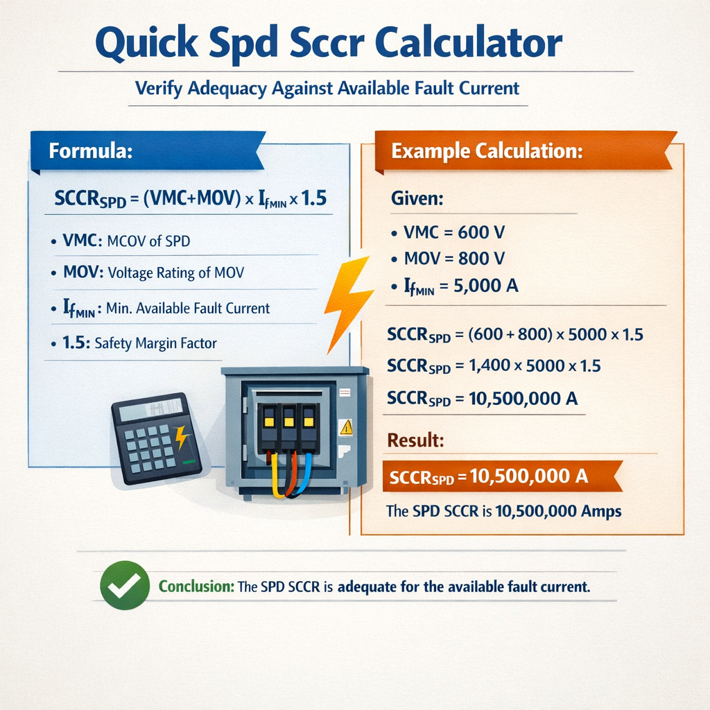
Quick SPD SCCR Adequacy Calculator vs. Available Fault Current
Background on SPD, SCCR and available fault current
Surge Protective Devices (SPDs) are installed to limit overvoltages from lightning and switching transients. The SPD Short-Circuit Current Rating (SCCR) defines the maximum prospective short-circuit current that the SPD can safely withstand without creating an additional hazard. If an SPD with insufficient SCCR is exposed to a higher available fault current at its point of installation, it may fail catastrophically, causing fire or equipment damage.Available fault current (I_avail) is the maximum prospective short-circuit current that can flow at a specific point in the system under bolted-fault conditions. Verification of SPD adequacy is therefore a two-step process: compute or obtain the available fault current at the SPD location, then ensure the SPD or its protective coordination (for example, a properly selected series fuse) provides protection such that the SPD will not be subjected to destructive currents beyond its SCCR.Regulatory framework and normative references
Compliant SPD selection and verification should reference relevant international and national standards and codes:- IEC 61643-11 – Surge protective devices connected to low-voltage power systems. Performance and testing requirements. (https://webstore.iec.ch/publication/2826)
- UL 1449 – Surge Protective Devices standard (United States). (https://standardscatalog.ul.com/standards/en/standard_1449)
- NFPA 70 (NEC) – National Electrical Code: Article 285 provides requirements for surge protective devices. (https://www.nfpa.org)
- IEEE C62.41 – Recommended practices on surge voltages in low-voltage AC power circuits. (https://standards.ieee.org)
- Manufacturer application guides and fuse standards (e.g., IEC 60269, UL fuses) for protection device selection and coordination.
Key parameters that influence verification
- Available fault current (I_avail) at the SPD installation point.
- SPD SCCR (stated by the manufacturer), usually in kA (rms symmetrical or peak depending on marking).
- SPD mode of protection and continuous operating voltage (Uc), nominal discharge current (In, 8/20 μs), and maximum discharge current (Imax).
- Upstream protective device type, rating, and time-current characteristic (fuse or circuit breaker), including interrupting rating (IR).
- System voltage, transformer MVA or kVA, impedance (Z%), and X/R ratio that influence waveform asymmetry.
- Installation location (service entrance, distribution panel, equipment branch) which determines NEC and local code requirements.
Calculation methodology — determine available fault current
To verify SPD adequacy you must first compute the available fault current at the installation point. Two common methods:- Use system single-line data: transformer kVA and percent impedance (Z%), or utility short-circuit MVA at the point of common coupling.
- Use measured or recorded utility/plant fault current data from coordination studies or protective relay logs.
Common formula for three-phase transformer-fed systems
Formula for three-phase bolted short-circuit current at the transformer's secondary terminals:
Where:
- I_sc = three-phase short-circuit current in amperes (A).
- S_kVA = transformer rated power in kVA.
- V_sec = secondary line-to-line voltage in volts (V).
- Z% = transformer percent impedance (per cent), typically provided on nameplate.
Typical values:
- S_kVA = 500 kVA (common distribution transformer)
- V_sec = 480 V
- Z% = 4% to 6% (varies with transformer)
Single-phase transformer or generator formula (simplified)
Where V is the phase voltage (line-to-neutral for single-phase).
Alternative using system short-circuit MVA
From utility fault MVA at a bus:
Where MVA_short is the symmetrical short-circuit MVA available at that bus.
SPD SCCR verification rule and interpretation
The basic rule for verification:- SPD SCCR (manufacturer-marked) must be equal to or greater than the available fault current at the SPD location: SCCR ≥ I_avail.
- If the SPD SCCR is less than I_avail, then the SPD must be protected by an upstream protective device (fuse or breaker) whose clearing performance limits the current seen by the SPD to a level that the SPD can safely withstand.
Common SPD and protective-device values (reference tables)
| SPD Type / Rating | Nominal discharge current In (8/20 µs) kA | Maximum discharge Imax (kA) | Typical SCCR marking (kA) | Typical application |
|---|---|---|---|---|
| Class II / Type 2 SPD | 10 | 20 | 10, 25, 50 | Distribution panels, branch panels |
| Combination Type 1+2 | 20 | 40 | 25, 50, 100 | Service entrance, main switchboards |
| High-energy industrial SPD | 40 | 100 | 50, 100, 200 | Critical plants, high exposure to lightning |
| Surge arresters (station class) | — | — | 100+ | Substation primary protection |
| Upstream protective device | Typical interrupting rating (A Symm or kA) | Role in SPD protection |
|---|---|---|
| Time-delay fuse (current-limiting) | Interrupting ratings up to 200 kA (depending on class) | Limits let-through energy (I2t) to protect SPD with lower SCCR |
| Circuit breaker (thermal-magnetic) | 6 kA to 100 kA depending on frame and rating | Primary branch protection; may not limit peak fault energy as fuses do |
| High-interrupting capacity breaker | 50 kA to 200 kA | Used where high available fault current must be interrupted safely |
Formulas and variable explanations
All formulas are expressed in plain HTML with variable descriptions and typical values.
Three-phase bolted short-circuit current at transformer secondary:
- S_kVA: transformer rating in kVA (typical: 150, 250, 500, 1000 kVA).
- V_sec: secondary line-to-line voltage in V (typical: 208 V, 400 V/415 V, 480 V).
- Z%: transformer percent impedance (typical: 4.0% to 10%).
Available fault current from utility short-circuit power:
- MVA_short: short-circuit MVA at the bus.
- V: system nominal voltage (line-to-line) in V.
Basic SPD adequacy verification (boolean check):
- SPD_SCCR: SPD short-circuit current rating in amperes (A) or kiloamperes (kA).
- I_avail: available fault current in same units.
If SPD_SCCR < I_avail then protective coordination required:
Select fuse such that I_peak_through_SPD ≤ SPD_SCCR and fuse IR ≥ I_avail.
Practical considerations for protective coordination
When the SPD SCCR is below the available fault current:- Install a suitably rated current-limiting fuse upstream that will clear a short-circuit quickly and limit let-through current (I_t) to below the SPD’s permissive energy and current levels.
- Verify the fuse interrupting rating (IR) is greater than the available fault current (or the short-circuit MVA equivalent) at that point.
- Ensure the SPD continuous current rating and thermal withstand match the system continuous currents and expected inrush events.
- Consult manufacturer time-current curves (fuse and SPD) and, where necessary, perform an I2t energy coordination check: the fuse must clear the fault before the SPD experiences destructive I2t energy.
Example 1 — Commercial 480Y/277 V distribution panel (complete worked example)
Scenario:- 500 kVA distribution transformer, secondary 480 V (line-to-line), nameplate impedance Z% = 5%.
- SPD to be installed at the distribution panel secondary.
- SPD candidate A: marked SCCR = 10 kA.
- SPD candidate B: marked SCCR = 50 kA.
- SPD A SCCR = 10 kA < I_avail (12.04 kA) → Not acceptable without additional protection.
- SPD B SCCR = 50 kA ≥ I_avail (12.04 kA) → Acceptable directly.
- Install a current-limiting fuse upstream with interrupting rating IR ≥ 12.04 kA (choose common fuse class with IR 100 kA available commercially).
- Select fuse ampere rating such that normal operation does not blow it; choose a fuse with suitable time-delay characteristic. Example: a 200 A class fuse with current-limiting characteristics.
- Check manufacturer let-through data: if the chosen fuse limits prospective peak and energy such that the SPD sees less than its maximum allowable Imax and I2t energy, coordination is acceptable.
- Direct accept: SPD B (50 kA SCCR) is an immediate fit.
- With coordination: SPD A may be possible if upstream fuse limits current to within SPD A ratings and fuse IR meets prospective fault current.
Example 2 — Industrial plant with high utility fault current (detailed calculation)
Scenario:- Utility reports short-circuit MVA at plant service bus = 200 MVA.
- Plant service voltage = 13.8 kV (feeder). SPD intended for a step-down 480/277 V distribution board located downstream of a 2000 kVA transformer with 6% Z.
- SPD candidate C has SCCR = 25 kA; SPD candidate D has SCCR = 100 kA.
- SPD C SCCR = 25 kA < I_avail (40.1 kA) → inadequate without series protection.
- SPD D SCCR = 100 kA > I_avail (40.1 kA) → adequate directly.
- Upstream overcurrent protective device must limit the current seen by the SPD to ≤ 25 kA. However, since prospective available fault current is 40.1 kA, a protective device must be current-limiting and able to reduce let-through below 25 kA.
- Select a current-limiting fuse with manufacturer let-through characteristics: choose fuse class and ampacity (for branch) with IR rating > 40.1 kA. Verify manufacturer data showing peak let-through at this prospective is < 25 kA and I2t exposure within SPD C’s allowable energy.
- If no fuse can achieve sufficient limitation, the SPD C is not acceptable and SPD D or relocation of SPD to a point with lower I_avail or using additional upstream impedance (e.g., series reactor) is required.
Choose SPD D if minimal engineering modification is desired. If SPD C must be used for budget reasons, extensive coordination calculations, selection of a high-performance current-limiting fuse (and possibly additional upstream impedance), and factory acceptance testing will be required.
Practical verification checklist for engineers
- Identify SPD installation point and gather single-line diagram details and transformer ratings or utility MVA data.
- Calculate I_avail using transformer kVA & Z% or use utility-provided short-circuit MVA.
- Record SPD nameplate SCCR and other relevant parameters (In, Imax, Uc).
- Perform direct comparison: if SPD_SCCR ≥ I_avail then SPD is acceptable.
- If SPD_SCCR < I_avail, evaluate upstream protective device options (fuse types) and check manufacturer let-through data and I2t coordination.
- Verify fuse interrupting rating (IR) ≥ I_avail and verify fuse clearing characteristics limit let-through to within SPD capability.
- Document calculations and include manufacturer data sheets and certificate of compliance (UL/IEC marks).
- Where required by code, provide field labeling and record SPD SCCR on as-built documentation.
Advanced topics: asymmetry, DC offset, and I2t energy checks
Real-world faults present asymmetrical currents and DC offsets. The manufacturer SCCR test methods assume certain test conditions; matching real asymmetrical fault peak values may require:- Consideration of X/R ratio and DC offset to estimate peak asymmetrical current from symmetrical RMS values. Peak may exceed RMS × √2 and thus stress the SPD more than indicated by RMS-only SCCR values.
- Applying transient modeling or referring to manufacturer short-circuit test reports to verify SPD withstand at specified X/R ratios.
- Performing I2t energy coordination: the upstream fuse must have an I2t let-through value lower than the SPD allowable I2t energy. Manufacturer test data for the SPD provides maximum permissible I2t or similar energy metric.
Documentation and audit trail for compliance
For each SPD installation, maintain the following:- Single-line excerpt showing point of SPD installation.
- Calculation sheet showing how I_avail was derived, including all variables and units.
- SPD manufacturer datasheet showing SCCR marking and test reports.
- Upstream protective device data including interrupting rating, time-current curves, and let-through tables.
- Proof of code compliance (UL listing, IEC certificate) and any required sign-off by a licensed engineer.
References and authoritative resources
- IEC 61643-11: Surge protective devices connected to low-voltage power distribution systems. https://webstore.iec.ch/publication/2826
- UL 1449 Standard for Surge Protective Devices. https://standardscatalog.ul.com/standards/en/standard_1449
- NFPA 70 (NEC) Article 285 — Surge Protective Device requirements. https://www.nfpa.org
- IEEE Std C62.41 — IEEE Guide on Surge Voltages in Low-Voltage AC Power Circuits. https://standards.ieee.org
- IEC 60269 and UL fuse standards for fuse selection and interrupting ratings.
Best practices summary for rapid SPD SCCR verification
- Always start with accurate system data (transformer kVA, Z%, utility MVA) — conservative assumptions otherwise.
- Prefer SPDs with SCCR comfortably greater than I_avail when space and budget allow to avoid complex coordination.
- When coordination required, use manufacturer coordination data (SPD + fuse) — do not rely on rule-of-thumb reductions without documented let-through figures.
- Document decisions, and ensure compliance with applicable national codes and listed device instructions.
- Engage equipment manufacturers early if available fault current is high or non-standard (high X/R, DC components) to validate SPD behavior under realistic fault conditions.